Craftsman 247.79452 User Manual
Page 16
Attention! The text in this document has been recognized automatically. To view the original document, you can use the "Original mode".
spider fails completely, you will experience a loss of
power.
ys WARNING: Never hit the engine shaft in
^1^ any manner, as a blow will cause permanent
damage to the engine or the pump.
Follow the instructions carefully as the alignment of
the couplings is critical.
» Disconnect the spark plug wire from the spark
plug, and keep it away from the spark plug.
•
Using a 1/2 Inch wrench, remove three nuts and
lock washers which secure the pump to the
coupling shield. Two nuts are at the bottom
corners and one is in the top center. See Figure
17. Remove the pump,
•
Remove the nylon spider insert from the
coupling and inspect for wear. Replace if
necessary.
•
Inspect the engine coupling half jaws for signs of
wear. Replace if necessary.
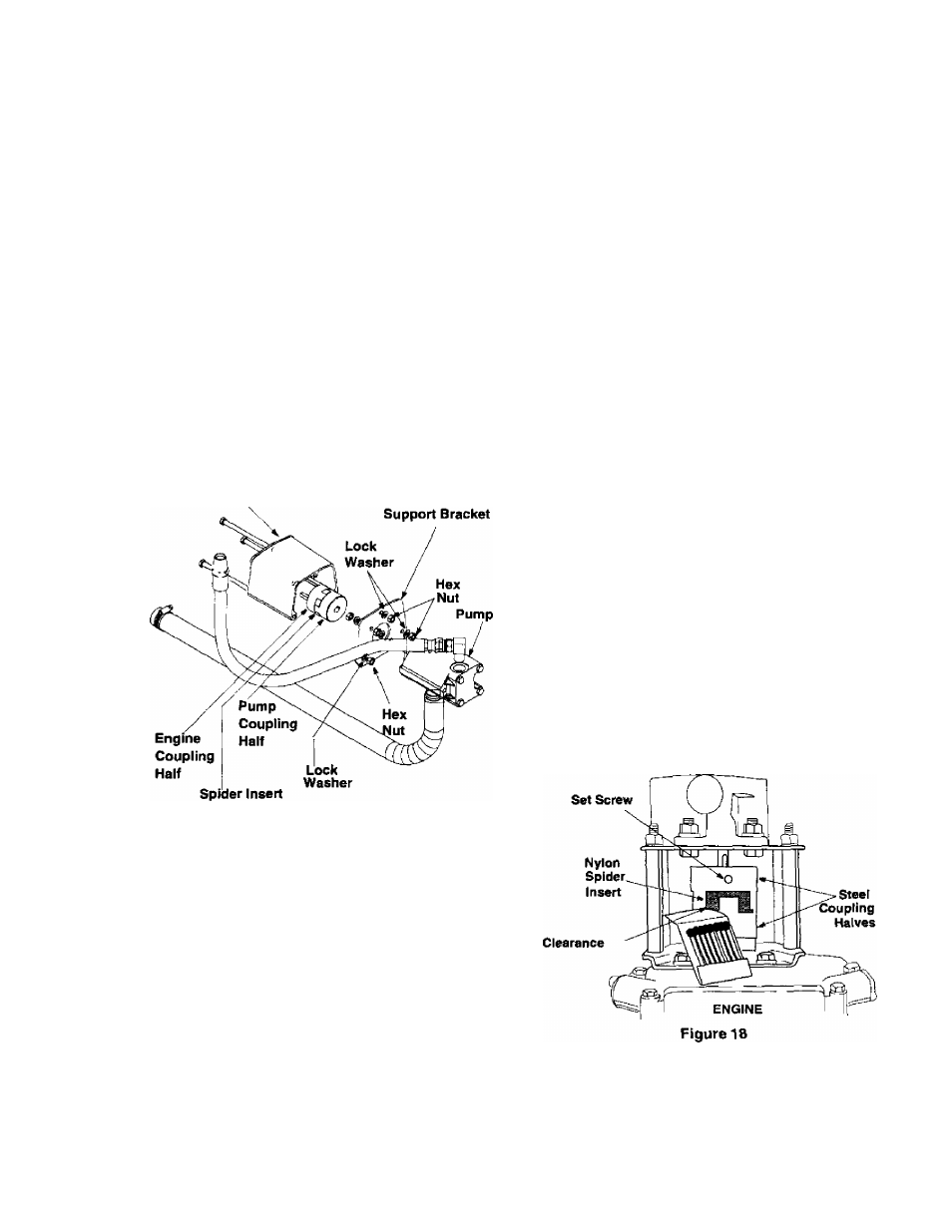
Coupling Shield
Rear Coupling
Figure 17
To replace engine coupiing haif: Rotate the
engine by pulling starter handle until engine
coupling half set screw is at bottom. Loosen set
screw using 1/8 inch alien wrench. Slide
coupling half off engine shaft. See Figure 17.
Install new coupling half on engine shaft making
sure to aiign key way in coupling half with key in
the engine shaft.
Slide coupler half along engine shaft until the
end of the shaft is flush with the inner portion of
the coupling half. {There must be space
between end of the engine support bracket and
the coupling half.) Apply Loctite’^“ to threads of
set screw and torque to 78 inch-pounds.
•
Inspect the pump coupling half jaws for signs of
wear. Replace if necessary.
•
To replace pump coupling half: Loosen set
screw using 1/8 inch alien wrench. Slide
coupling half off pump shaft.
•
Install new coupling half on pump shaft making
sure to align key way in coupling half with key in
pump shaft. Rotate coupiing half until set screw
faces down. Do not tighten set screw now.
•
Install new spider insert on to the engine
coupling half.
•
Align pump coupling half with nylon “spider'’ by
rotating engine using starter handle.
•
Slide coupling half into place while guiding three
mounting bolts through holes in pump support
bracket.
Note:
The pum p coupling half can be rotated by hand
to aid in alignm ent. If the two parts are not aligned
right, the unit w ili not operate properly and dam age
could occur.
•
Secure with nuts and washers removed earlier.
•
Set .035 to .060 inch clearance between the
nylon "spider" and the engine coupling half by
sliding a matchbox cover between the nylon
“spider” and the engine coupling half and
moving pump coupling half as needed. See
Figure 18.
•
Apply Loctite'^'^ to threads of set screw. Tighten
set screw to torque 78 inch-lbs. This should
secure the pump coupling half.
■ Reattach spark plug wire to spark plug.
PUMP
16