Craftsman 917.293301 User Manual
Page 16
Attention! The text in this document has been recognized automatically. To view the original document, you can use the "Original mode".
TIRE CARE
A
ca
UTION: When mounting tires, un
less beads are seated, overinflation can
cause an explosion.
® Maintain 20 pounds of tire pressure. If
tire pressures are not equal, tiller will
pull to one side,
o Keep tires free of gasoline or oil which
can damage rubber.
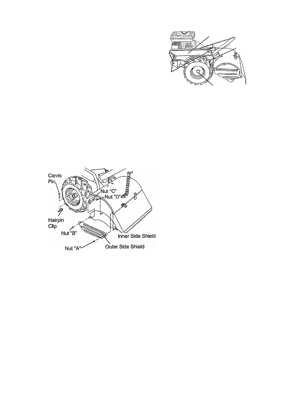
TO REMOVE WHEEL
® Place blocks under transmission to keep
tiller from tipping.
® Remove outer side shield by removing
nuts “A” and “B”.
® Remove inner side shield by removing
nuts
“C”
and “D”.
® Remove hairpin clip and clevis pin from
wheel
^ Remove wheel and tire.® Repair tire and
reassemble.
Beit Guard
TO REMOVE BELT OUARD
MOTE: For ease of removal, remove hair
pin clip and clevis pin from left wheel Pull
wheel out from tiller about 1 inch.
» Remove two (2) cap nuts and washers
from side of belt guard.
» Remove hex nut and washer from bot
tom of belt guard (located behind
wheel).
<» Pull belt guard out and away from unit.
# Replace belt guard by reversing above
procedure.
Hex Nut and
Washer
(Located
Behind Tire)
Cap Nut
and
Washer
Hairpin Clip and Clevis Pin
TO REPLACE OROUND DRIVE
BELT
® Remove belt guard as described in ‘TO
REMOVE BELT GUARD".
® Loosen belt guides "A” and “B" and
also remove stud “C".
® Remove old belt by slipping off engine
pulley first then remove from the pulley.
8 Place new belt in groove of transmis
sion pulley and into engine pulley, BELT
MUST BE IN GROOVE ON TOP OF
IDLER PULLEY. NOTE POSITION OF
BELT TO GUIDES.
8 Tighten belt guides “A” and “B” and stud
“C”.
8 Check belt adjustment as described
below.
8 Replace belt guard.
8 Reposition wheel and replace clevis pin
and hairpin clip.
ground
drive
BELT ADJUST
MENT
For proper belt tension, the extension
spring should have about 5/8 Inch stretch
when drive corttrol bar is in “ENGAGED"
position. This tension can be attained as
follows:
8 Loosen cable clip screw securing the
drive control cable.
8 Slide cable forward for less tension and
rearward for more tension until about 5/8
Inch stretch is obtained while the drive
control bar is engaged.
8 Tighten cable clip screw securely.
16