Crestron tps-impc interface module – Crestron electronic TPS-IMPC User Manual
Page 9
Crestron TPS-IMPC
Interface
Module
CAUTION: The 10-pin RJ-45 net/video connector cable supplied by
Crestron is a custom cable and is the only one that should be used. The
end of the cable has a metal shield that is required to protect the
equipment. Using non-Crestron cables will result in damage to the
product.
AUDIO (To Panel)
AUDIO
1
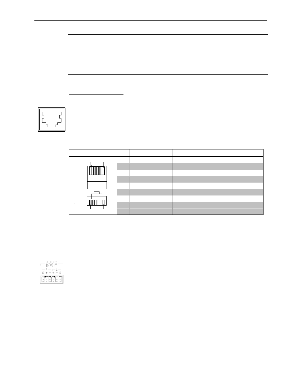
This 8-pin RJ-45 mates with the TPS-3000, TPS-5000, or TPS-6000
touchpanel. The 8-pin audio cable assembly is supplied. Even though the
10-pin net/video cable may fit into the port, do not use it. This port
provides audio input to the touchpanel and microphone output from the
touchpanel. A description of the pinouts is shown in the following table.
AUDIO Pinouts
TYPE PIN DESIGNATION
DESCRIPTION
1
L+
Left Input (Positive)
2
L-
Left Input (Negative)
3 GND/Shield
Audio
Input
Ground/Shield
4
R+
Right Input (Positive)
5
R-
Right Input (Negative)
6
GND/Shield
Mic Output Ground/Shield
7
M+
Mic Output (Positive)
1
8
1
8
Front
Top
8
M-
Mic Output (Negative)
To determine the location of pin 1, hold the cable so that the end of the
8-pin RJ-45 connector is facing away from you, with the clip side down
and the copper side up. The copper connector on the far left is pin 1.
AUDIO INPUT
The port mates with a six-pin connector (supplied) and provides balanced
and/or unbalanced audio input. Description of the pinouts is shown in the
following table.
Operations Guide - DOC. 6162
Interface Module: TPS-IMPC
• 5