Interface module crestron tps-impc – Crestron electronic TPS-IMPC User Manual
Page 8
Interface Module
Crestron TPS-IMPC
CAUTION: If power is provided to the TPS-IMPC from the +24VDC on
a Cresnet connector or the PW-2420RU, power must not be applied to
the power input on the touchpanel base.
NOTE: When power is supplied through this connector, Crestron
recommends disconnecting the +24 VDC on the Cresnet connector (if it
is connected).
NOTE: Use care in wiring installations to avoid applying 24 VDC power
to Cresnet wiring from multiple sources.
NET/VIDEO (To Panel)
VIDEO
NET/
1
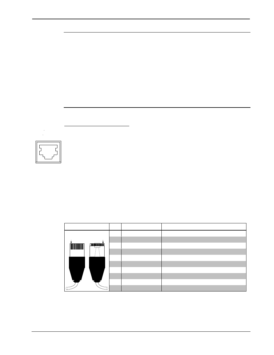
This 10-pin RJ-45 connection mates with the TPS-3000, TPS-5000, or
TPS-6000 touchpanel. Refer to the descriptions and pinout table that
follow this paragraph. The 10-pin net/video cable assembly to connect
the touchpanel to the TPS-IMPC is supplied. Even though the 8-pin audio
cable may fit into the port, do not use it.
This port provides the Cresnet connection to the touchpanel. This port
also provides composite or S-video input for the built-in video card (with
the purchase of a TPS-3000 or installation of the TPS-VID-1/2 in a
TPS-5000 or TPS-6000 touchpanel). Consult the latest revision of the
TPS-3000 Operations Guide (Doc. 6076) or TPS-VID-1/2 Operations &
Installation Guide (Doc. 6059) for details.
NET/VIDEO Pinouts
TYPE PIN DESIGNATION
DESCRIPTION
1 +24V
Power
(Network)
2
GND
Ground (Network)
3
C+
Chrominance (Positive) /Composite 2
4
C-
Chrominance (Negative) /Composite 2
5 Y
Data
(Network)
6
Z
Data (Network)
7
Y+
Luminance (Positive)/Composite 1
8
Y-
Luminance (Negative)/Composite 1
9 GND
Ground
(Network)
10-pin RJ-45
Pin 1
Pin 1
10
+24V
Power (Network)
To determine the location of pin 1, hold the cable so that the end of the
10-pin RJ-45 connector is facing away from you, with the clip side down
and the copper side up. The copper connector on the far left is pin 1.
4
• Interface Module: TPS-IMPC
Operations Guide - DOC. 6162