Crestron tps-impc interface module – Crestron electronic TPS-IMPC User Manual
Page 13
Crestron TPS-IMPC
Interface
Module
TPS-5000 or TPS-6000 touchpanel and a video window object resides on
a page within the uploaded Crestron VisionTools
®
Pro-e (VT Pro-e)
project.
NOTE: When connecting the net/video cable from the interface module
to the touchpanel, exceeding a cable length of 30 feet will significantly
degrade the video signal. To maintain high-quality video, DO NOT
daisy-chain cables or Crestron TPSBLOCK-10 cables longer than 30
feet. Contact Crestron for the maximum available cable length.
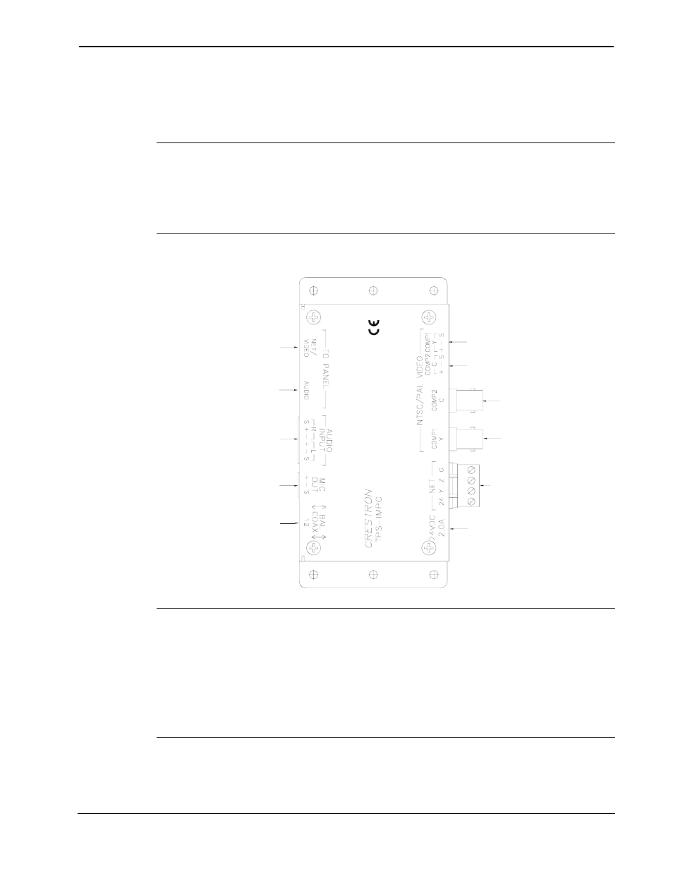
Hardware Hookup for the TPS-IMPC
SELECT BALANCED (TWISTED
PAIR) OR COAX (UNBALANCED)
FOR EACH VIDEO SIGNAL
CONNECT TO DEVICE
AUDIO INPUT
CONNECT TO
AUDIO SOURCE
CONNECT TO 10-POSITION
NET/VIDEO PORT ON
TOUCHPANEL
CONNECT TO
8-POSITION AUDIO PORT
ON TOUCHPANEL
(BLUE)
BALANCED "Y" FOR S-VIDEO OR
COMPOSITE VIDEO
UNBALANCED "C" FOR
S-VIDEO OR COMPOSITE 2
FOR COMPOSITE VIDEO
(TPS-VID-2 ONLY)
BALANCED "C" FOR S-VIDEO OR
COMPOSITE 2 FOR COMPOSITE
VIDEO (TPS-VID-2 ONLY)
UNBALANCED "Y"
FOR S-VIDEO OR
COMPOSITE VIDEO
CONNECT TO CONTROL
SYSTEM OR CRESNET
PERIPHERALS
CONNECT OPTIONAL POWER
PACK PW-2420RU
NOTE: The included AUDIO cable has a connector with a blue cover to
match the blue connector on the TPS-IMPC. As older AUDIO cables
may not have the blue cover, be sure to insert the AUDIO cable into the
AUDIO port.
NOTE: Do not confuse the 8-pin audio cable with the 10-pin net/video
cable.
Operations Guide - DOC. 6162
Interface Module: TPS-IMPC
• 9