Intrepid ii woodburning stove – Vermont Casting 1990 User Manual
Page 8
8
Intrepid II Woodburning Stove
2000966
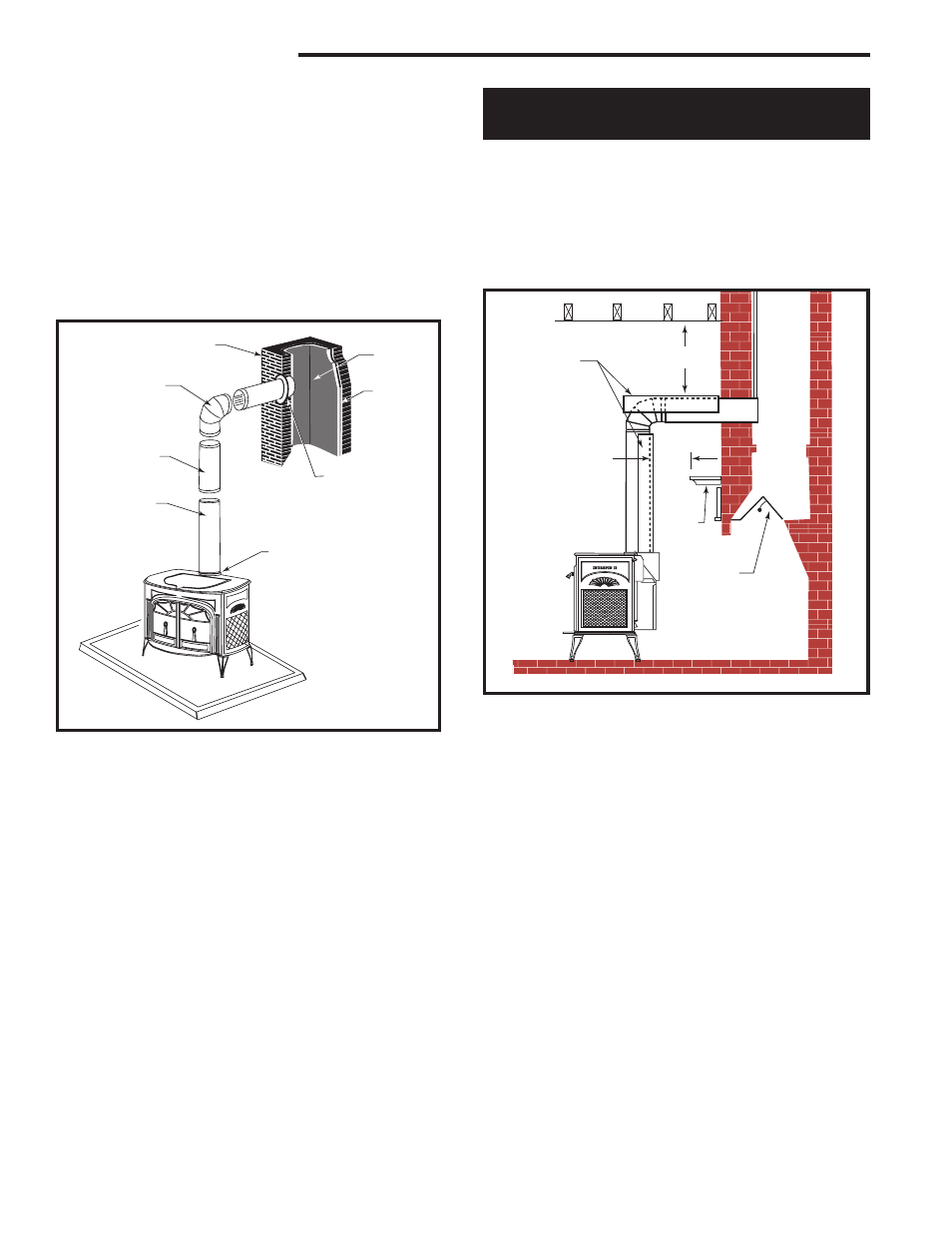
The opening through the chimney wall to the flue (the
“breach”) must be lined with either a ceramic or metal
cylinder, called the “thimble”, which is cemented firmly
in place. The fit must be snug and the joint between the
thimble and the chimney wall must be cemented. (Fig.
6)
A special piece called the “thimble sleeve,” slightly
smaller in diameter than standard connector and most
thimbles, will facilitate the removal of the chimney con-
nector system for inspection and cleaning. Thimble
sleeves should be available from your local dealer. (Fig.
5)
To install a thimble sleeve, slide it into the breach until
it is flush with the inner flue wall. Do not extend it into
the actual flue passage, as this could interfere with the
draft.
The thimble sleeve should protrude 1-2” (25-50 mm)
into the room. Use furnace cement and thin gasketing
to seal the sleeve in place in the thimble. Secure the
chimney connector to the outer end of the sleeve with
sheet metal screws.
Without a thimble, a suitable length of chimney con-
nector can be extended through the breach to the inner
face of the flue liner, and cemented securely in place.
Additional pieces of connector are then attached with
sheet metal screws.
Fireplace Chimney Installations -
Above a Fireplace
The Intrepid II may be connected to a chimney above a
fireplace opening also. In such installations, the stove is
positioned on the hearth in front of the fireplace and the
chimney connector rises from the stove top and then
angles ninety degrees back into the chimney. (Fig. 7)
The chimney liner should extend to the point at which
the chimney connector enters the chimney.
If the chimney connector from your installation enters
the chimney above a fireplace, follow all the guidelines
mentioned above for freestanding installations. In addi-
tion, give special consideration to the following points:
•
Check the clearance between the stove and the
chimney connector, and any combustible trim or the
mantel. Use the necessary combination of mantel,
trim, and connector heat shields to achieve the re-
quired clearances.
•
Check the clearance between the chimney connec-
tor and the ceiling. If no heat shields are used, the
clearance should be at least 26” (660mm). To find
out how much this clearance may be reduced with
heat shields, see the clearance chart on Page 14.
•
The fireplace damper must be sealed to prevent
room air from escaping up the flue. However, it must
be possible to re-open the damper to inspect or
clean the chimney.
ST492a
Intrepid II
freestanding
installation
11/00
INTRE
PID II
Chimney
Elbow
Slip Pipe
Standard
Chimney
Connector
Flue Collar
Flue
Flue
Liner
Thimble
ST492a
Fig. 6 Chimney connection in a freestanding installation.
ST244
Plymouth
fplc over mantel
12/99
Chimney Connector
Shields
* Check
These Clear-
ances
*
*
Mantel
Seal the
Damper
ST244
Fig. 7 Chimney connector enters chimney above the firep.
lace.