Intrepid ii woodburning stove, Alcove installations, Construction requirements – Vermont Casting 1990 User Manual
Page 13
13
Intrepid II Woodburning Stove
2000966
Noncombustible shields installed 1” (25 mm) away from
the combustible surface on noncombustible spacers,
called ventilated shields, may be used to reduce clear-
ances. (Fig. 14)
1" (25mm)
1/4" (6mm)
ST501
mantel and
trim shield
11/10/00 djt
ST501
Fig. 14 A custom-formed mantel shield.
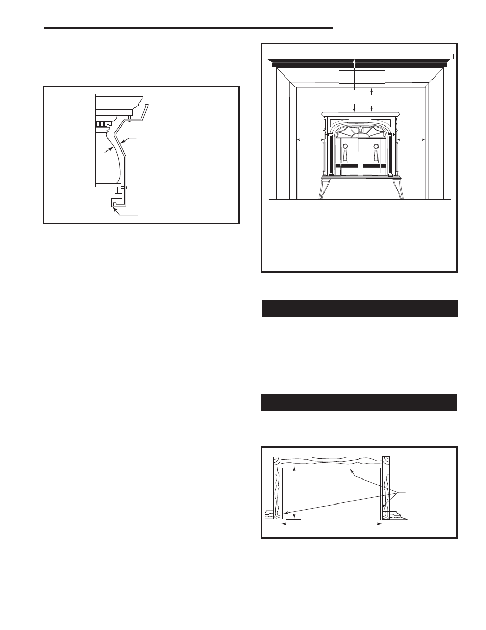
To protect a mantel from the heat of an Intrepid II in a
fireplace installation, the ventilated mantel shield must
be at least 48” (1220 mm) long, and it must be centered
over the stove. Ventilated shields for side trim must
extend the full length of the trim.
An unprotected mantel (‘A’, Fig. 15) cannot be more
than 9” (230 mm) deep and must have a minimum
clearance of 30” (760 mm), measured from the stove’s
top plate. With a ventilated shield, this clearance may
be reduced safely to 14” (360 mm).
Unprotected top trim (B) protruding 2” (50mm) or less
from the face of the fireplace must be a minimum of 24”
(610 mm) from the stove’s top surface. With a venti-
lated trim shield, this clearance may be reduced safely
to 14” (360 mm).
Unprotected side trim (C) that protrudes 2” (50mm) or
less from the face of a fireplace must have a minimum
clearance of 15” (380mm), measured from the stove’s
top side edge. With a ventilated trim shield, the clear-
ance may be reduced safely to 10” (254 mm). If the trim
extends more than 2” (51 mm), wall clearance require-
ments apply.
The charts and sample installations that follow list the
clearances required for the various installation configu-
rations of the Intrepid II.
ST253
trim clearances
12/15/99 djt
C
C
A
B
ST253
Fireplace Mantel and Trim Clearances
Measured from the top and sides of the stove
A. Mantel
30” (762 mm)
14” (356 mm)
B. Top Trim
24” (610 mm)
14” (356 mm)
C. Side Trim
15” (381 mm)
10” (254 mm)
Unprotected
Protected
Fig. 15 Maintain clearances to combustible components of
the mantelpiece.
Alcove Installations
Because of their restricted air flow and heat retention
characteristics, specific construction requirements and
special clearances apply to installations into alcoves.
No stove or chimney connector heat shields are used
in alcove installations.
ALCOVE INSTALLATION OF THE INTREPID II IS
NOT PERMITTED IN CANADA.
Construction Requirements
The following illustrations show noncombustible ceiling
framing and maximum and minimum permitted dimen-
sions for alcove construction.
36"
Max.
48" Min.
ST502
Intrepid
Alcove floor plan
11/10/00 djt
Use recommended
floor protection
7/16” Durock®
(or equivalent)
spaced 1” off
wood studs on
noncombustible
spacers
ST502
Fig. 16 Alcove floor plan. Sheetrock on front face butts to
Durock® (or equivalent) alcove lining.