Vermont Casting 1990 User Manual
Page 18
18
Intrepid II Woodburning Stove
2000966
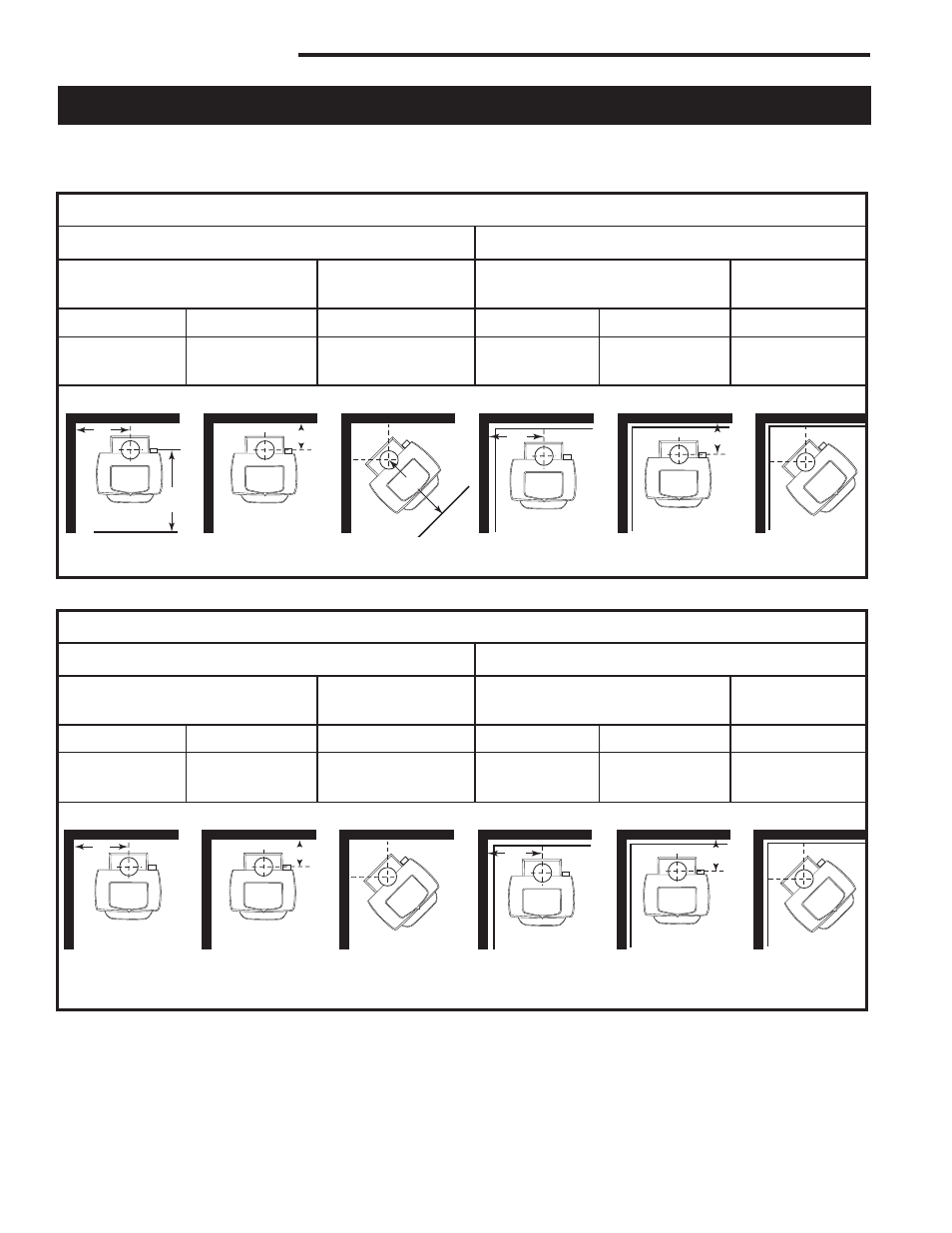
Distance from the Center of the Flue Collar to the Wall in Top-Exit Installations
The information on this page is helpful in planning stove placement for top-exiting installations, particularly those in-
stallations with chimneys that pass through the ceiling. However, this is not a clearance chart. Final stove clearances
must adhere to the guidelines stated in the clearance charts on Page 14.
** To locate center of flue collar for corner installation, add 7” (180mm) to the clearance distance form stove corner to wall. Mark off the resulting
distance from the corner along both walls. Next, measure the same distance form these two points out from the walls. These last two measure-
ments will meet at a point representing the center of the flue collar. Refer to the diagrams above.
Side (A)
Rear (B)
Corner (C)
Side (D)
Rear (E)
Corner (F)
34³⁄₄”
15”
18³⁄₄”
22³⁄₄”
8”
16³⁄₄”
(883 mm)
(381 mm)
(476 mm)
(578 mm)
(203 mm)
(426 mm)
Parallel Installations
Corner
Installations**
Corner
Installations**
Parallel Installations
Intrepid II: WITH Stove and Chimney Connector Heat Shields
Unprotected Surfaces
Protected Surfaces
ST511a
Intrepid
flue centerline
Diagrams
11/16/00
A
B
C
D
E
F
ST511a
Side (A)
Rear (B)
Corner (C)
Side (D)
Rear (E)
Corner (F)
34³⁄₄”
29”
26³⁄₄”
22³⁄₄”
15”
16³⁄₄”
(883 mm)
(737 mm)
(680 mm)
(578 mm)
(381 mm)
(426 mm)
Parallel Installations
Corner
Installations**
Corner
Installations**
Parallel Installations
Intrepid II: WITHOUT Stove and Chimney Connector Heat Shields
Unprotected Surfaces
Protected Surfaces
ST51
Intrepid
flue centerline
Diagrams
11/16/00
*
A
B
C
*
D
E
F
ST511
* This distance, from the center of the flue collar to the front edge of the hearth, is the same for all installations on this page: 31” in the United
States and 33” (840mm) in Canada.