Camera and microphone assembly, Remove the camera/microphone assembly (see, Removing the camera and microphone assembly – Dell Vostro 1310 (Early 2008) User Manual
Page 21: Remove the camera and microphone assembly (see, Replacing the display cable
Replacing the Display Cable
1.
Connect the display cable to the connector on the back of the display panel.
2.
Replace the display panel (see
).
3.
Connect the camera/microphone cable to the connector on the camera/microphone assembly.
4.
Replace the camera and microphone assembly (see
Replacing the Camera and Microphone Assembly
5.
Replace the two M2 x 5-mm screws in the hinges.
6.
Replace the display inverter (see
Replacing the Display Inverter
7.
Replace the display bezel (see
).
8.
Replace the display assembly (see
Replacing the Display Assembly
9.
Replace the keyboard (see
Replacing the Keyboard
).
10.
Replace the hinge cover (see
Replacing the Hinge Cover
).
11.
Replace the WLAN card (see
Replacing a WLAN Card
).
12.
Replace the hard drive (see
Replacing the Hard Drive
).
Camera and Microphone Assembly
Removing the Camera and Microphone Assembly
1.
Follow the instructions in
Before Working on Your Computer
.
2.
Remove the hard drive (see
Removing the Hard Drive
).
3.
Remove the WLAN card (see
Removing a WLAN Card
).
4.
Remove the hinge cover (see
Removing the Hinge Cover
).
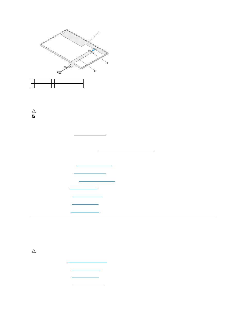
1 display panel 2 display cable connector
3 display cable
CAUTION:
Before you begin the following procedure, follow the safety instructions that shipped with your computer.
NOTE:
This procedure assumes that you have completed the removal procedure first.
CAUTION:
Before you begin the following procedure, follow the safety instructions that shipped with your computer.