Display-assembly interface cable, Display-assembly interface cable -37, Figure 4-23 – Dell Latitude Cpi User Manual
Page 73: Lvsod\$vvhpeo\,qwhuidfh&deoh
Removing and Replacing Parts
4-37
'LVSOD\$VVHPEO\,QWHUIDFH&DEOH
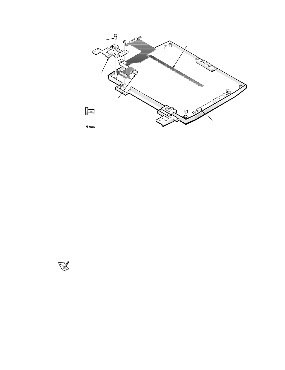
)LJXUH 'LVSOD\$VVHPEO\ ,QWHUIDFH &DEOH 5HPRYDO
,QFK 'LVSOD\ 6KRZQ
5HPRYH WKH GLVSOD\ DVVHPEO\
5HPRYH WKH /&' SDQHO
'LVFRQQHFW WKH GLVSOD\DVVHPEO\ LQWHUIDFH FDEOH IURP =,) FRQQHF
WRU - RQ WKH /&' LQYHUWHU ERDUG
5HPRYH WKH WZR PP VFUHZV VHFXULQJ WKH OHIW KLQJH DQG WKHQ
UHPRYH WKH KLQJH IURP WKH GLVSOD\DVVHPEO\ WRS FRYHU
,I \RX DUH UHPRYLQJ WKH GLVSOD\DVVHPEO\ LQWHUIDFH FDEOH IURP D
LQFK GLVSOD\ UHPRYH WKH OHIW WRSFRYHU EUDFH IURP WKH
GLVSOD\DVVHPEO\ WRS FRYHU VHH )LJXUH
To remove the top cover brace, remove the 3-mm screw securing it.
/LIW WKH GLVSOD\DVVHPEO\ LQWHUIDFH FDEOH RXW RI WKH GLVSOD\
DVVHPEO\ WRS FRYHU
NOTE: When replacing the display assembly, reinstall the screws securing the
left hinge at the locations marked on the hinge by arrows. Ensure that the
display-assembly interface cable wraps once around the plastic bobbin before
connecting the cable to the system board.
display-assembly interface cable
connector J1
left hinge
plastic bobbin
5-mm
screws (2)