Video connector, Infrared port – Dell Inspiron 5000 User Manual
Page 32
If the television has an S-video cable, plug it directly into the computer at the TV-out S-video connector. If the television has a composite cable, perform the following
steps:
1. Connect the cable that came with your computer to the TV-out S-video connector.
2. Connect the other end of the cable to the television composite cable.
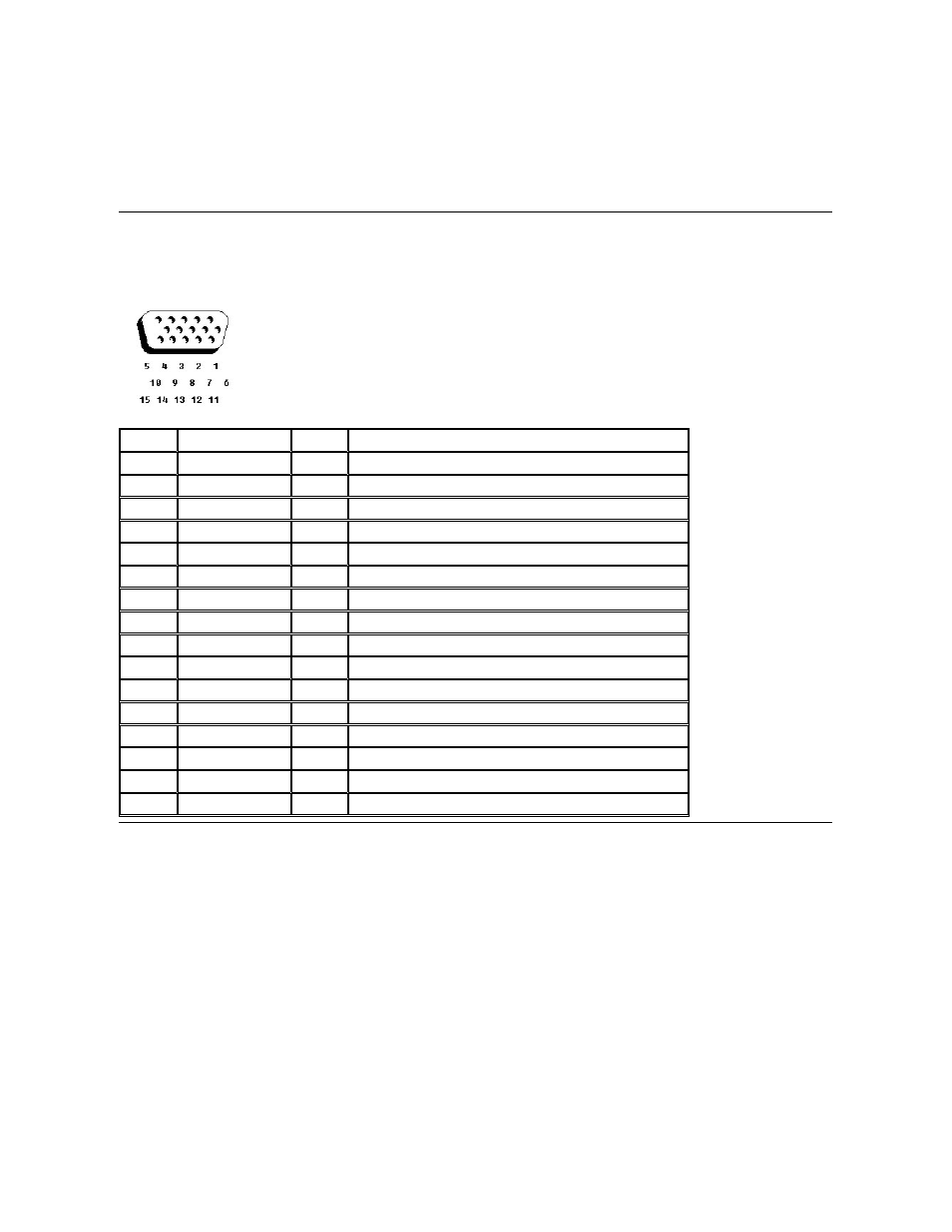
Video Connector
Use the 15-pin video connector to attach an external monitor to the computer. If the image does not appear on the monitor immediately, press
Infrared Port
The infrared port is IrDA 1.1-compliant. An infrared data stream is transmitted through a lens in the computer, up to a distance of 1 meter (m), and received by a
compatible computer, printer, mouse, or remote control. The infrared port allows the transfer of files from one computer to another infrared-compatible device, without
using cable connections. Dell has installed data communications software for you to use with the infrared port. You can also use other commercially available infrared-
capable application programs. For information on configuring the standard infrared drivers that come with Microsoft® Windows® 98, see your operating system
documentation. To install the fast infrared drivers provided by Dell, see the instructions in the readme.doc file on your System Software CD. If for some reason you
need to change the infrared port address, be careful not to create a conflict with the addresses of the serial port or the parallel port.
To use the infrared port, point the infrared port directly at the infrared port of the compatible device. Infrared devices transmit data in a 30° cone of infrared light. Start
the data communications software on both devices, and then begin transferring files. Read the documentation that came with your compatible device to make sure you
operate it correctly.
Pin
Signal
I/O
Definition
1
RED
O
Red video
2
GREEN
O
Green video
3
BLUE
O
Blue video
4
DDC2_MONID2
I
Monitor detect ID2
5
GND
N/A
Signal ground
6
GND
N/A
Signal ground
7
GND
N/A
Signal ground
8
GND
N/A
Signal ground
9
CRTVCC
O
5-V power source for CRT
10
GND
N/A
Signal ground
11
M-SEN#
I
Digital monitor sense/monitor detect ID1
12
DDC_DATA
I
Monitor detect serial data
13
HSYNC
O
Horizontal synchronization
14
VSYNC
O
Vertical synchronization
15
DDC_CLK
I
Monitor detect serial clock
Shell
N/A
N/A
Frame ground