System board – Dell Dimension 2200 User Manual
Page 66
66
Adding Parts
www
.dell.com | support.dell.com
System Board
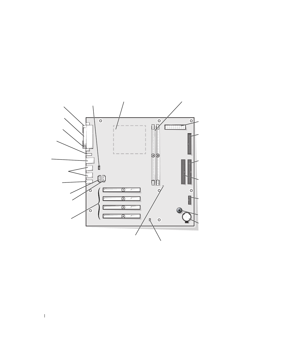
In the illustration, the text in parentheses indicates how items are identified
on the system board.
USB connectors
(USB 01, USB 23)
video
connector (VID)
parallel
connector (PAR)
serial
connector (SER)
PCI card connectors
(PCI1, PCI2,
microprocessor socket
(MICROPROCESSOR)
secondary IDE channel
connector (IDE 2)
control panel
connector (FRONT
PANEL)
floppy drive
interface connector
(DSKT)
primary IDE channel
connector (IDE 1)
power input
connector (POWER)
battery socket
(BATTERY) page 89
password jumper
DIMM sockets
(DIMM_A, DIMM_B)
keyboard/mouse
connectors (KEYBD
MOUSE)
power indicator (AUX PWR)
speaker (SPEAKER)
fan connector
(FAN)
diagnostic lights
(DIAG LED)
microphone, line-out,
line-in (AUDIO)
modem
connector (MODEM)
CD connector (CD IN)
- Inspiron 530 (2 pages)
- OptiPlex 755 (622 pages)
- OptiPlex 755 (528 pages)
- OptiPlex 755 (82 pages)
- OptiPlex 755 (45 pages)
- OptiPlex 755 (248 pages)
- OptiPlex 760 (76 pages)
- OptiPlex 760 (203 pages)
- OptiPlex 745 (428 pages)
- OptiPlex 745 (212 pages)
- OptiPlex 745 (360 pages)
- OptiPlex 780 (89 pages)
- OptiPlex 780 (10 pages)
- OptiPlex 780 (74 pages)
- OptiPlex 780 (80 pages)
- OptiPlex 780 (73 pages)
- OptiPlex 780 (40 pages)
- OptiPlex 780 (14 pages)
- OptiPlex GX620 (221 pages)
- OptiPlex GX620 (294 pages)
- OptiPlex GX620 (338 pages)
- Inspiron 530 (226 pages)
- OptiPlex 960 (Late 2008) (16 pages)
- OptiPlex GX260 (100 pages)
- OptiPlex GX260 (235 pages)
- OptiPlex FX160 (Late 2008) (20 pages)
- OptiPlex FX160 (Late 2008) (132 pages)
- OptiPlex FX160 (20 pages)
- OptiPlex 210L (128 pages)
- OptiPlex 210L (300 pages)
- OptiPlex 210L (258 pages)
- OptiPlex 210L (150 pages)
- OptiPlex 210L (130 pages)
- OptiPlex 320 (266 pages)
- OptiPlex 320 (356 pages)
- OptiPlex 320 (44 pages)
- OptiPlex 320 (140 pages)
- OptiPlex 320 (132 pages)
- OptiPlex 320 (312 pages)
- OptiPlex GX240 (144 pages)
- OptiPlex GX240 (121 pages)
- OptiPlex GX240 (86 pages)
- OptiPlex GX240 (283 pages)
- OptiPlex GX240 (298 pages)
- OptiPlex GX240 (182 pages)