Crestron electronic TPMC-8T User Manual
Page 13
Crestron TPMC-8T
Isys i/O™ 8.4” TableTop WiFi Touchpanel
Connectors, Controls & Indicators (Continued)
# CONNECTORS,
CONTROLS &
INDICATORS
DESCRIPTION
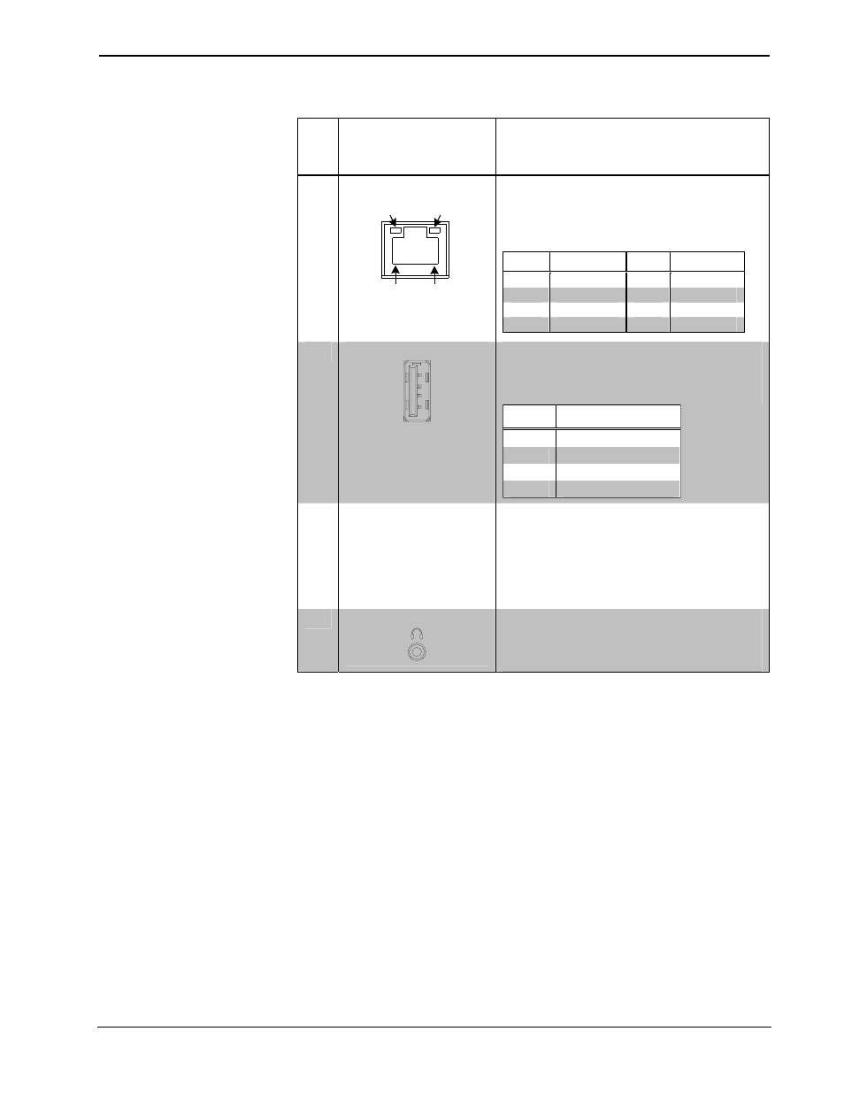
10
LAN
4
GREEN
LED
YELLOW
LED
PIN 8
PIN 1
(1) 8-wire RJ-45 with two LED indicators;
10BASE-T/100BASE-TX Ethernet port;
Green LED indicates link status;
Yellow LED indicates Ethernet activity
PIN
SIGNAL
PIN
SIGNAL
1
TX +
5
N/C
2
TX -
6
RC -
3
RC+
7
N/C
4
N/C
8
N/C
11
USB
1
2
3
4
(3) USB 2.0 Type A female
USB 2.0 port for keyboard, mouse and
computer console
5
PIN
DESCRIPTION
1
+5 VDC
2
Data -
3
Data +
4
Ground
12 POWER
BUTTON (1) pushbutton, initiates “Power On” and
Power Down”:
Press to turn touchpanel power on; Press
and hold for four seconds to turn power off
(The recommended method for shutting
down the touchpanel is to press the Shut
Down button on the setup menu.)
13
HEADPHONES
(1) 3.5 mm TRS mini phone jack;
Stereo headphone output;
Output power: 12 mW per channel;
Minimum impedance: 32 Ω
1. Refer to website or contact Crestron for a current list of compatible devices and embedded
applications. To ensure reliable performance, new device drivers and applications are available only
from Crestron through firmware updates.
2. For programming details, refer to “Hard Buttons” on page 31.
3. Crestron recommends using either the power jack on the base or on the side of the panel but not both
at the same time.
4. To determine which is pin 1 on the cable, hold the cable so that the end of the eight pin modular jack
is facing away from you, with the clip down and copper side up. Pin 1 is on the far left.
5. Only generic USB devices (i.e. simple keyboard, mouse and external storage) should be used with the
TPMC-8T. Any complex USB devices (e.g. a storage device with a built-in fingerprint scanner) will
not have the proper support on the panel.
Operations Guide – DOC. 6567C
Isys i/O™ 8.4” TableTop WiFi Touchpanel: TPMC-8T
• 9