Interpreting led activity – Dell PowerEdge M805 User Manual
Page 32
22
4424 Blade Server SAN I/O Module Hardware Reference Manual
53-0000571-01
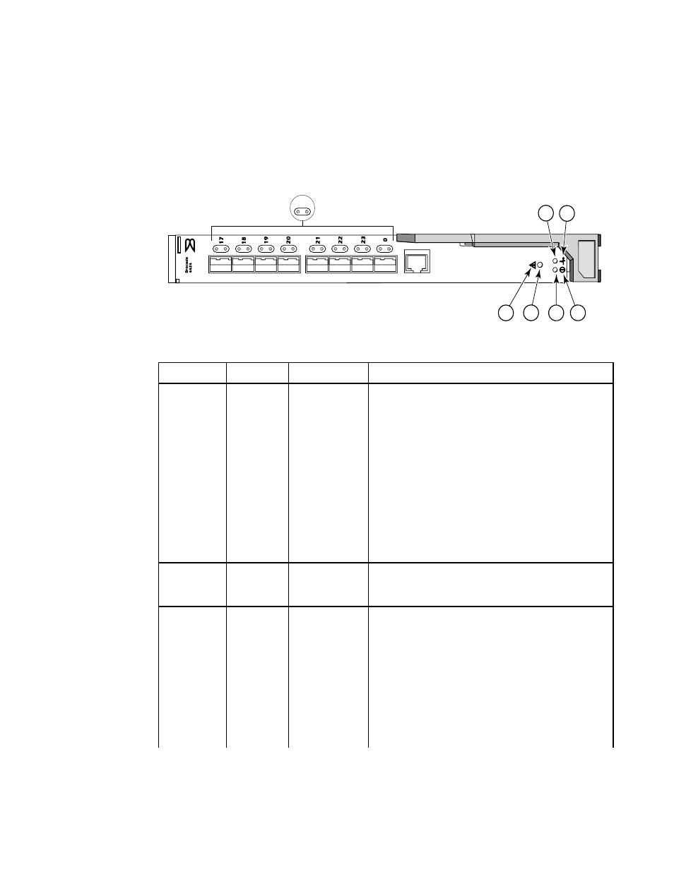
Interpreting LED activity
3
Interpreting LED activity
Each SAN I/O Module uses LEDs to indicate status. These LEDs are shown in
FIGURE 5
LED Locations
TABLE 4
Location
Indicator
Color
Operation
1
FC (external)
port status
green/amber
Note: LED meanings are not valid during boot, diagnostics,
or POST.
Green:
Off (dark): No signal carrier or unlicensed.
Steady: Online normal active port but no port activity.
Flickering: normal active port (I/O activity).
Slow blink: Online but segmented.
Fast blink: Internal loopback.
Amber
Steady: Signal present but not online.
Slow blink or flash: Disabled port (less than two second
interval).
Fast (rapid) blink or flash: Error or fault with port (less than
1/2 second interval).
2
FC port x
speed
green/amber
Amber on: 4 Gbit/sec FC
Green on: 2 Gbit/sec FC
Both off (dark): 1 Gbit/sec FC
3 (status icon)
and 4 (LED)
module
status
green/amber
Off:
SAN I/O Module is off or power supplies for the Blade Server
or onboard DCC have failed.
Green:
No errors and all ports are ready for use.
Amber:
Steady: Boot-up state, port(s) offline, or in reset state.
Blinking (green/amber): One or more environmental ranges
are exceeded, or error log contains diagnostic error
messages.
Note: The LED might blink during testing.
IOIOI
1 2
3
4
5
6
7
8