360 dvs series direct vent fireplaces, Mantels, Clearance to combustibles – Vermont Casting 360DVS3 User Manual
Page 7: Hearth
8
360 DVS Series Direct Vent Fireplaces
10006326
CFM170
DV Builder Front
View
O
N
M
L
K
Appliance
Top .........................................0” (0 mm) to standoff
Bottom ..................................................... 0” (0 mm)
Vent End ....................... 1/2” (13 mm) to rear panel
Nonvent End (DVS2) .............................. 0” (0 mm)
Venting
Concentric sections of DV Vent:
Top, bottom & sides .............................. 1” (25 mm)
Nonconcentric sections of DV Vent:
Side and bottom .................................... 1” (25 mm)
Top ........................................................ 2” (51 mm)
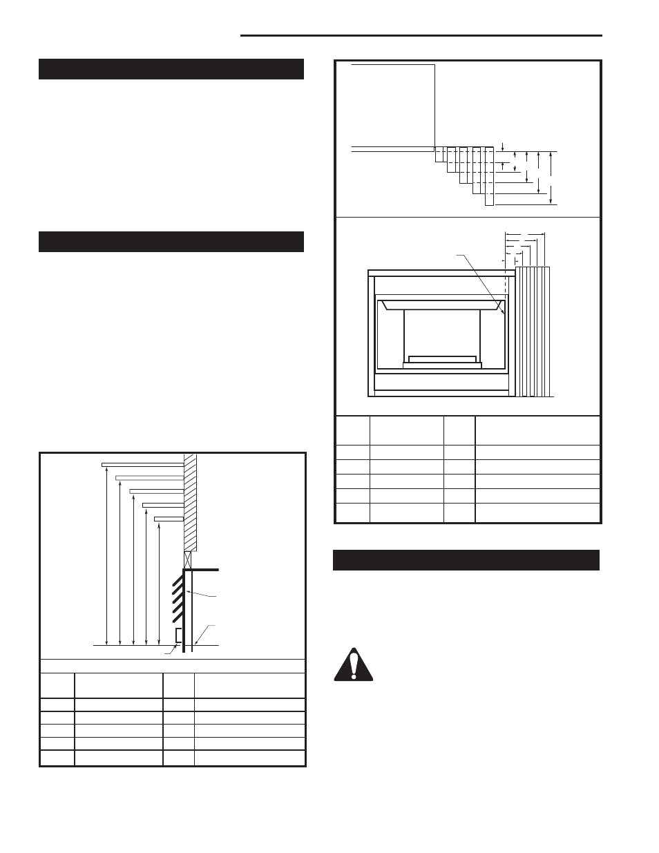
Mantels
The height at which a combustible mantel is fitted
above the fireplace is dependent on the depth of the
mantel. This also applies to the distance between the
mantel leg (if so fitted) and the fireplace. For correct
mounting height and width, refer to Fig. 4a and 4b and
the Mantel Chart below.
The fitting of a bay window trim kit does not affect the
distances and reference points referred to in the dia-
gram and chart.
Noncombustible mantels and legs may be installed at
any height and width around the appliance.
When using paint or lacquer to finish the mantel, such
paint or lacquer must be heat resistant to prevent dis-
coloration.
Clearance to Combustibles
A B C D E
V
W
X
Y
Z
CFM146
DV Mantel Chart
7/5/01 sta
Louvre Assembly
Top
Fireplace
Top of Combustion
Chamber
Bottom of Door Trim
Mantel Shelf
Mantel from Top
Ref. or Breast Plate Ref. of Comb. Chamber
V
10” (254 mm)
A
19” (483 mm)
W
8” (203 mm)
B
17” (432 mm)
X
6” (152 mm)
C
15” (381 mm)
Y
4” (102 mm)
D
13” (330 mm)
Z
2” (51 mm)
E
11” (297 mm)
Mantel Chart
CFM146
Fig. 4a Combustible mantel minimum installation.
J
F
G
H
I
CFM197
Mantel Corner Leg Chart
04/16/02 sta
Top View
Mantel Leg
CFM197
Front View
Side of Combustion
Chamber
Mantel
Leg
CFM170
Mantel
Mantel Leg From Side
Ref.
Leg Depth
Ref.
of Comb. Opening
F
10” (254 mm)
K
11¹⁄₂” (292 mm)
G
8” (203 mm)
L
9¹⁄₂” (241 mm)
H
6” (152 mm)
M
7¹⁄₂” (191 mm)
I
4” (102 mm)
N
5¹⁄₂” (140 mm)
J
2” (51 mm)
O
3¹⁄₂” (89 mm)
Fig. 4b Combustible mantel leg minimum installation.
A hearth is not mandatory; however, for aesthetic
purposes, we recommend installing a noncombustible
hearth that projects out 12” (305mm) or more from the
front of the fireplace.
Cold climate installation recommendation:
When installing this unit against a noninsu-
lated exterior wall or chase, it is mandatory
the outer walls be insulated to conform to
applicable insulation codes.
Hearth