Upgrading the emm-e6, B.1 locating brim connectors, Appendix b – Cabletron Systems EMM-E6 User Manual
Page 51: Details the procedures that must, Appendix b upgrading the emm-e6
EMM-E6 Installation Guide
B-1
APPENDIX B
UPGRADING THE EMM-E6
This appendix describes how to incorporate additional or expanded
capabilities into the EMM-E6. This appendix describes the procedures for
the addition of a BRIM or EPIM module and the addition of Single
In-line Memory Modules (SIMMs).
B.1
LOCATING BRIM CONNECTORS
This section points out Bridge Router Interface Module (BRIM)
connector locations on your EMM-E6 board. Refer to your BRIM Guide
for specific installation procedures and additional information.
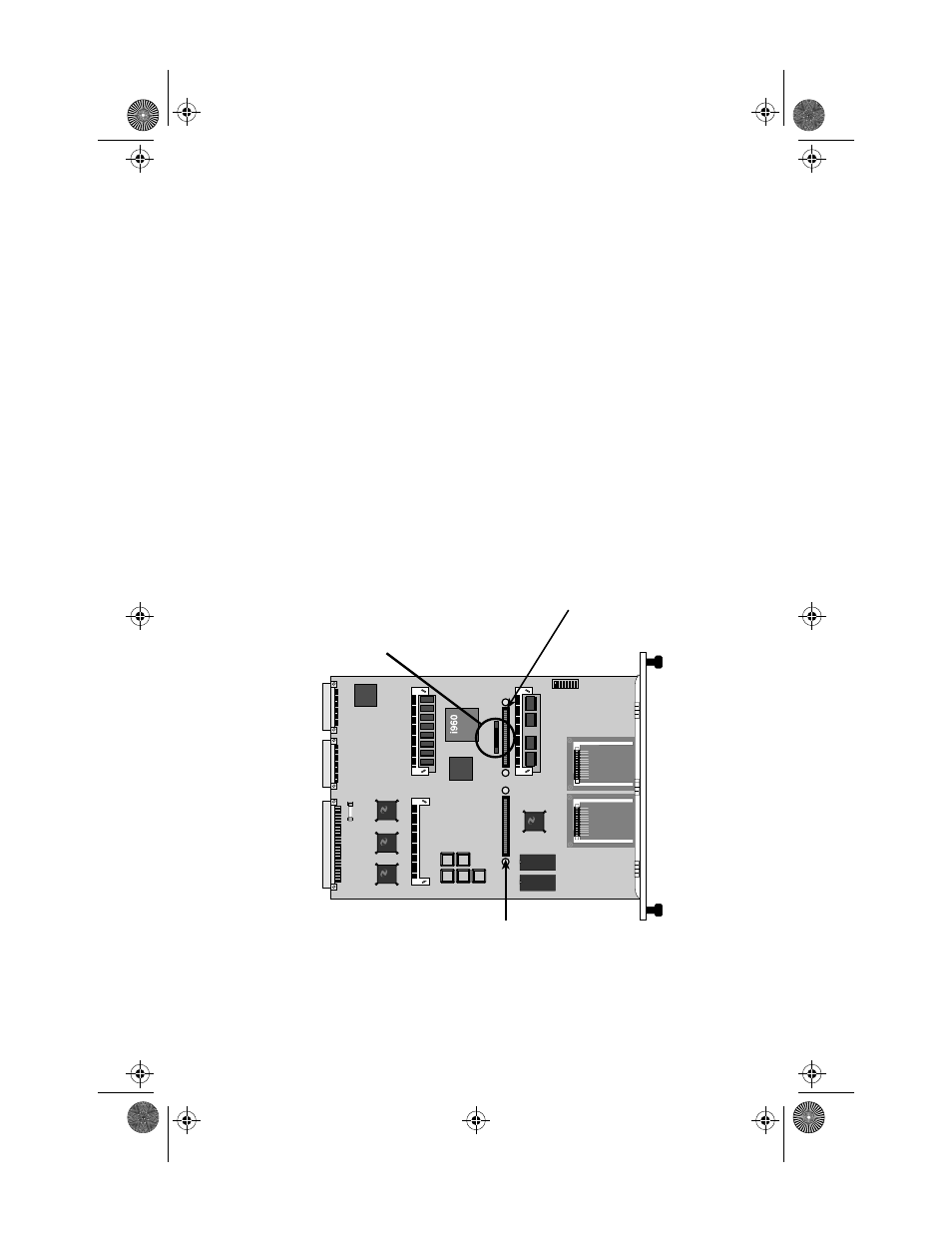
The following diagram (Figure B-1) shows BRIM connector locations for
the EMM-E6:
Figure B-1
BRIM Connector Locations
LSI
Logic
LSI
Logic
Channel E BRIM Connector
BRIM-F Ribbon Connector
Channel F BRIM Connector
1926n15
ICH1Book Page 1 Tuesday, August 6, 1996 3:06 PM