Wn in figure 2-2 and figure 2-3 – Cabletron Systems EMM-E6 User Manual
Page 15
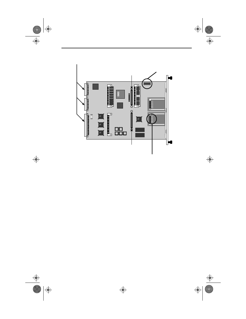
Internal Components
EMM-E6 Installation Guide
2-3
Figure 2-2
EMM-E6 Internal Components
Chassis Backplane Connections
The EMM-E6 connects to the backplane buses of the MMAC chassis
through these multipin connectors.
Dip Switch Bank
The EMM-E6 provides a bank of eight dual-position, or “dip” switches.
Several of these switches are used for testing purposes during the
manufacturing process. The dip switches can also be used to clear the
NVRAM of the EMM-E6, which contains configuration and local
management settings, or to force the EMM-E6 to request a new firmware
image from a properly configured BootP server.
BRIM Connectors
The Channel E and Channel F BRIM connectors allow the EMM-E6 to
connect BRIM modules to Ethernet Channels E and F of the EMM-E6.
LSI
Logic
LSI
Logic
Channel E BRIM Connector
Dip Switch Bank
Chassis Backplane Connections
Channel F BRIM Connector
EPIM Connector Pins
1926n02
ICH1Book Page 3 Tuesday, August 6, 1996 3:06 PM