Controls and indicators, 1 the faceplate, Chapter 2 – Cabletron Systems EMM-E6 User Manual
Page 13: The faceplate -1, Identifies and describes the, Chapter 2 controls and indicators
EMM-E6 Installation Guide
2-1
CHAPTER 2
CONTROLS AND INDICATORS
This chapter identifies and describes the components and operational
indicators of the EMM-E6.
2.1
THE FACEPLATE
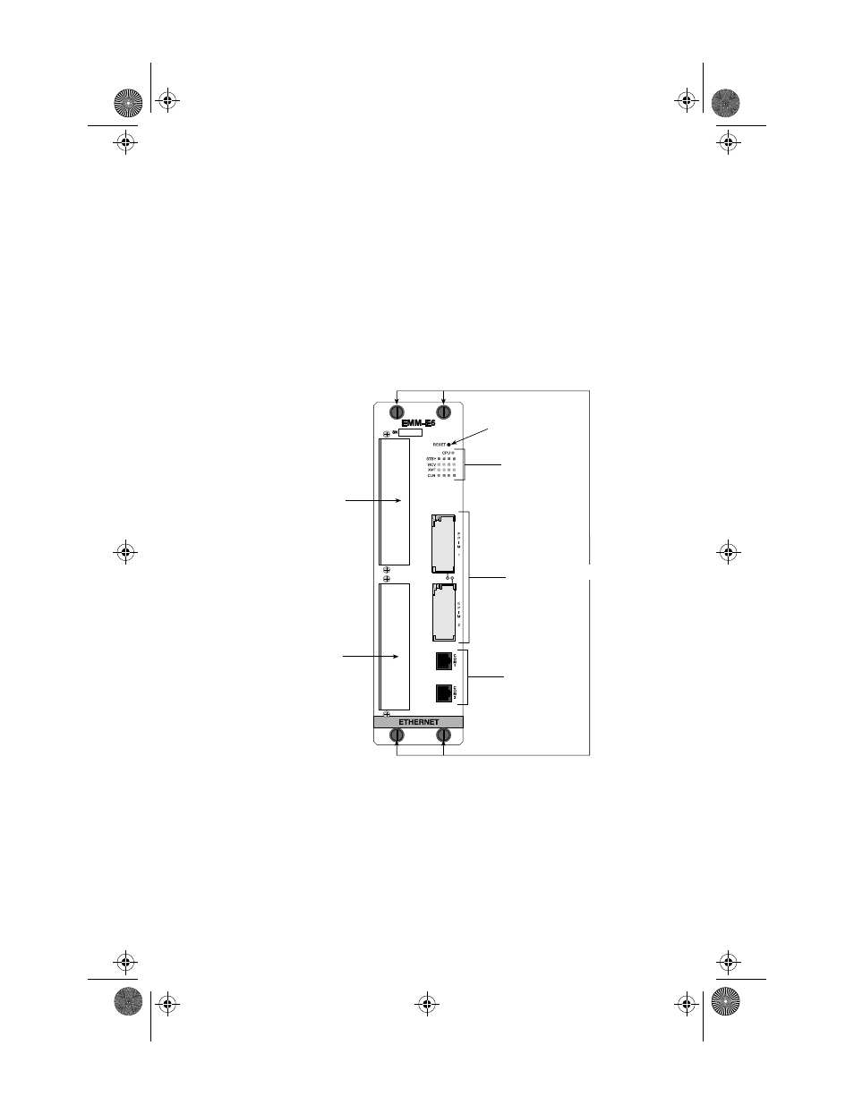
Figure 2-1
The EMM-E6 Faceplate
Knurled Knobs
The black plastic knurled knobs on the faceplate of the EMM-E6 are used
to turn the securing screws that hold the EMM-E6 module in place in the
MMAC chassis.
Interface E BRIM Slot
Interface F BRIM Slot
EPIM Slots
Serial Ports
Reset Switch
LANVIEW LEDs
Knurled Knobs
1926n01
E
F
ICH1Book Page 1 Tuesday, August 6, 1996 3:06 PM