Typical wiring schematic (cont) – Carrier 50AH User Manual
Page 12
12
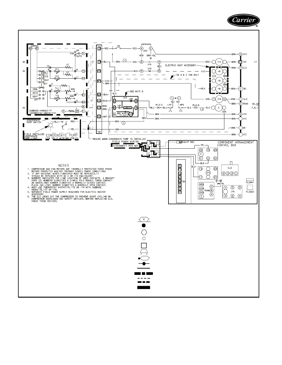
Typical wiring schematic (cont)
50AH036,048,060 — 208/230-3-60 UNITS
LEGEND
AHA
— Adjustable Heat Anticipator
C
— Contactor Compressor
CB
— Circuit Breaker
CC
— Cooling Compensator
CLO
— Compressor Lockout
CT
— Current Transformer
EQUIP GND — Equipment Ground
HPS
— High-Pressure Switch
HR
— Heater Relay
IFC
— Indoor (Evaporator) Fan Contactor
IFR
— Indoor (Evaporator) Fan Relay
JB
— Junction Box
L
— Light
LOR
— Lockout Relay
LPS
— Low-Pressure Switch
NEC
— National Electrical Code
PL
— Plug Assembly
TB
— Terminal Block
TC
— Thermostat-Cooling
TH
— Thermostat-Heating
TRAN
— Transformer
Marked Wire
Denotes connection point between subbase and thermostat
Terminal (Marked)
Terminal (Unmarked)
Terminal Block
Field Splice
Splice (Marked)
Factory Splice
Factory Wiring
Accessory or Optional Wiring
Field Control Wiring
Field Power Wiring
To indicate common potential only not to represent wiring
- 42S (72 pages)
- 30GT (4 pages)
- 48SS060 (8 pages)
- 50ME (54 pages)
- 38AH024-034 (26 pages)
- ZC (28 pages)
- 30GA (12 pages)
- COMFORTLINK 48A2 (8 pages)
- 48HE003---006 (64 pages)
- 33ZCSECTRM (52 pages)
- 19XRV (40 pages)
- MODU-PAC 50DF (37 pages)
- 17DA (8 pages)
- SINGLE PACKAGED ELECTRIC COOLING UNITS 50GS (28 pages)
- 48JZ (N) 024-060 (30 pages)
- 30GX080-176 (8 pages)
- 50DL (24 pages)
- 50GL-A (4 pages)
- NP034-074 (72 pages)
- 40GXQ (12 pages)
- 30XA080-500 (8 pages)
- 39E (12 pages)
- 40KMQ------301 (10 pages)
- 38AE (12 pages)
- 48AW (118 pages)
- 38GXQ (28 pages)
- 48ES---A (38 pages)
- 48GL (22 pages)
- 48GH (22 pages)
- 40QA024-060 (24 pages)
- TJF004 (52 pages)
- 39LD (40 pages)
- 48DL (4 pages)
- 48/50TC04---28 (44 pages)
- 50EJ (56 pages)
- 17EX (120 pages)
- 50BA (24 pages)
- 50BB (16 pages)
- 50BB (8 pages)
- 50BJ (20 pages)
- 30H (16 pages)
- 48HJD005-007 (48 pages)
- 50ZP (6 pages)
- 50DP016 (16 pages)
- 50LJ008-014 (19 pages)