2 digital sensor connection (iq), 3 binary input and push button – Dynalco SWT-1000 Speed Switch/Transmitter User Manual
Page 6
Operating
Instructions
SWT-1000
DYNALCO
SWT-1000.r2.0609
4
2.2.2 Digital Sensor Connection (IQ)
Frequency range (-3dB)
0.01 Hz / 35 kHz
Input impedance
46 K
Input voltage
Max. ± 36V peek
Minimum pulse width
Min. pulse width 1.5 µs
Sensor supply
+14 V, max. 35 mA short circuit proof.
If the current limit activates, the sensor supply must be disconnected to
reset the protection.
Trigger level
• min.U
low
= 1.6 V
• max.U
high
= 4.5 V
Screen
A terminal is provided for the sensor cable screen. This terminal is
connected to the sensor supply 0V. (0VS)
Sensor monitoring
1 of 2 settings may be configured via software:
• No
Sensor
Monitoring
• Monitoring of powered sensors
[Also for 2 wire sensors supplied via the Pull-up resistor (Jumper J1)
].
Æ The sensor is considered to be defective if the sensor current
consumption falls outside of I
min
and I
max
.
I
min.
= 0.5…25mA
I
max.
= 0.5…25mA
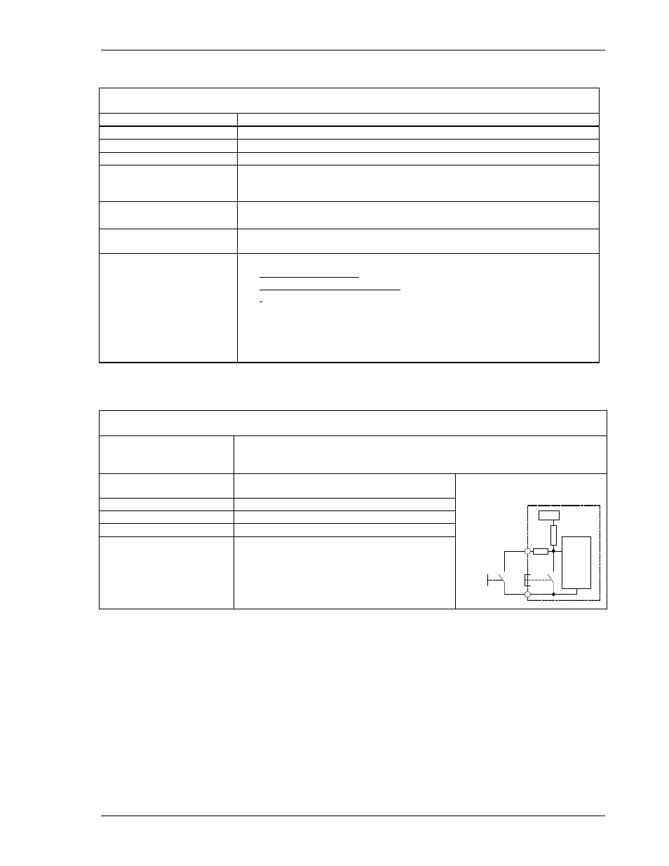
2.2.3 Binary Input and Push Button
Use
For external selection of Parameter set A or B.
• Logic 1 = Parameter set A (Relay control A)
• Logic 0 = Parameter set B (Relay control B)
Levels
Logic 1
= V > +3.5V
Logic 0
= V < +1.5V
Reference
Sensor supply 0V
Max voltage
36V
Input resistance
R
min
= 10k
Ω
Circuit
Internal pull up resistance to 5V
Shorting the binary input to the sensor 0V
creates logic 0.
5 volts
SWT-1000
parameter set A B
analysis
+Bin
OVS
pushbutton