Warning, Assembly – Bercomac Subframe & Drive Mechanism for JOHN DEERE Series X300 User Manual
Page 16
14
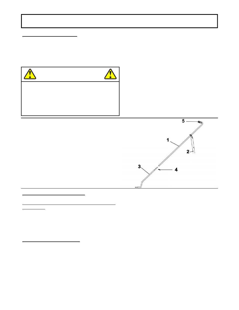
ASSEMBLY
Insert handgrip (item 5) on the handle (item 1).
Insert the handle (item 1) through the support (item 2)
as shown.
Install the handle on the control rod (item 3) as shown
and secure with a 2.5 mm. hair pin (item 4).
ADJUST THE LIFT SYSTEM:
Use the adjustable link to obtain the desired lift height
(maximum 4").
NOTE: The adjustment gauge (on the tractor) for the
height of the mower deck must be in the lowest
position (position 1). See tractor owner’s manual for
more information.
VERIFY TIRE PRESSURE:
Check and adjust tractor tire pressure as follows:
Front tires:
13-14 psi
Back tires:
9-10 psi
Tire pressure must be even on both sides of the
tractor.
Install handle
VERIFY BELT ROUTING:
-Lower the rotary broom to the ground and let it run
for a few seconds under supervision.
-Disengage the rotary broom and stop the engine.
-Check the belts to make sure they are well inserted
on the pulleys and have not flipped on their sides in
the pulleys and that they do not touch the belt guides
WARNING
TO PREVENT INJURIES:
It is the person who installs the drive mechanism
responsibility to make sure that when the clutch is
disengaged that all moving parts stop.
For more information, do not hesitate to contact
the technical support.
- Subframe & Drive Mechanism for JOHN DEERE Series X304 Subframe & Drive Mechanism for JOHN DEERE Series X320 Subframe & Drive Mechanism for JOHN DEERE Series X324 Subframe & Drive Mechanism for JOHN DEERE Series X340 Subframe & Drive Mechanism for JOHN DEERE Series X500 Subframe & Drive Mechanism for JOHN DEERE Series X520 Subframe & Drive Mechanism for JOHN DEERE Series X534 Subframe & Drive Mechanism for JOHN DEERE Series X540