3power supply options, 1battery, 2ac adapter – Cooper Instruments & Systems DPG 100 Digital Pressure Test Gage User Manual
Page 10: 3external vehicle (dc) power supply, 4turning the instrument on and off, 5zeroing the display, Power supply options, Battery, Ac adapter, External vehicle (dc) power supply
3.3
Power Supply Options
3.3.1 Battery
Two nine-volt alkaline batteries (NEDA 1604) are recommended operation. This is a common type of battery that is
available at many stores. With two alkaline batteries, the instrument can operate continuously on for approximately
3 weeks. Carbon-zinc batteries (sometimes labeled as "general purpose" or "heavy duty") should not be used.
Please note that the temperature specifications of the batteries you purchase may not be the same as those of the
instrument.
If two batteries are not available, the instrument will operate with only one alkaline battery installed in either clip.
However, this will reduce the continuous operation time to approximately one-and-a -half weeks.
The use of two lithium batteries will allow your instrument to operate continuously for over 6 weeks.
To install the batteries:
Important note: The brown wire of the sensor cable must be on the right as you face the circuit board, as shown
in the figure in Section 4.4. If you connect the sensor cable backwards, the instrument will not operate correctly.
• Remove the center screw on the back of the instrument.
• Remove the front face panel from the case.
• The colored ribbon cable extending from the sensor to the electronics may be disconnected to make the
battery installation more convenient.
• Replace the batteries one at a time, making sure of the correct polarity.
• Reconnect the sensor cable to the electronics.
• Replace the front face panel.
• Carefully replace the rear center screw.
Note: Calibration and setup values are stored in a nonvolatile memory, and are not lost during battery replacement.
3.3.2 AC Adapter
The wall mount power supply allows the instrument to operate from a North American standard 110 VAC, 60 Hz
outlet. Connect the plug at the end of the supply's cord into the socket on the rear of the instrument. An optional
European 220VAC, 50Hz wall mount supply is also available. See "Power Adapter Specification" in Chapter 8.
3.3.3 External Vehicle (DC) Power Supply
Some instruments operate from an external DC power source. You will need 11 to 32 VDC at 30 mA.
At the rear of the instrument is a gland fitting that secures the power supply wiring. The wiring code is given below:
Table 2: Vehicle power wiring code
Wire Designation
Red
(+)Supply (11-32 VDC)
Black Supply
Return
3.4
Turning the Instrument On and Off
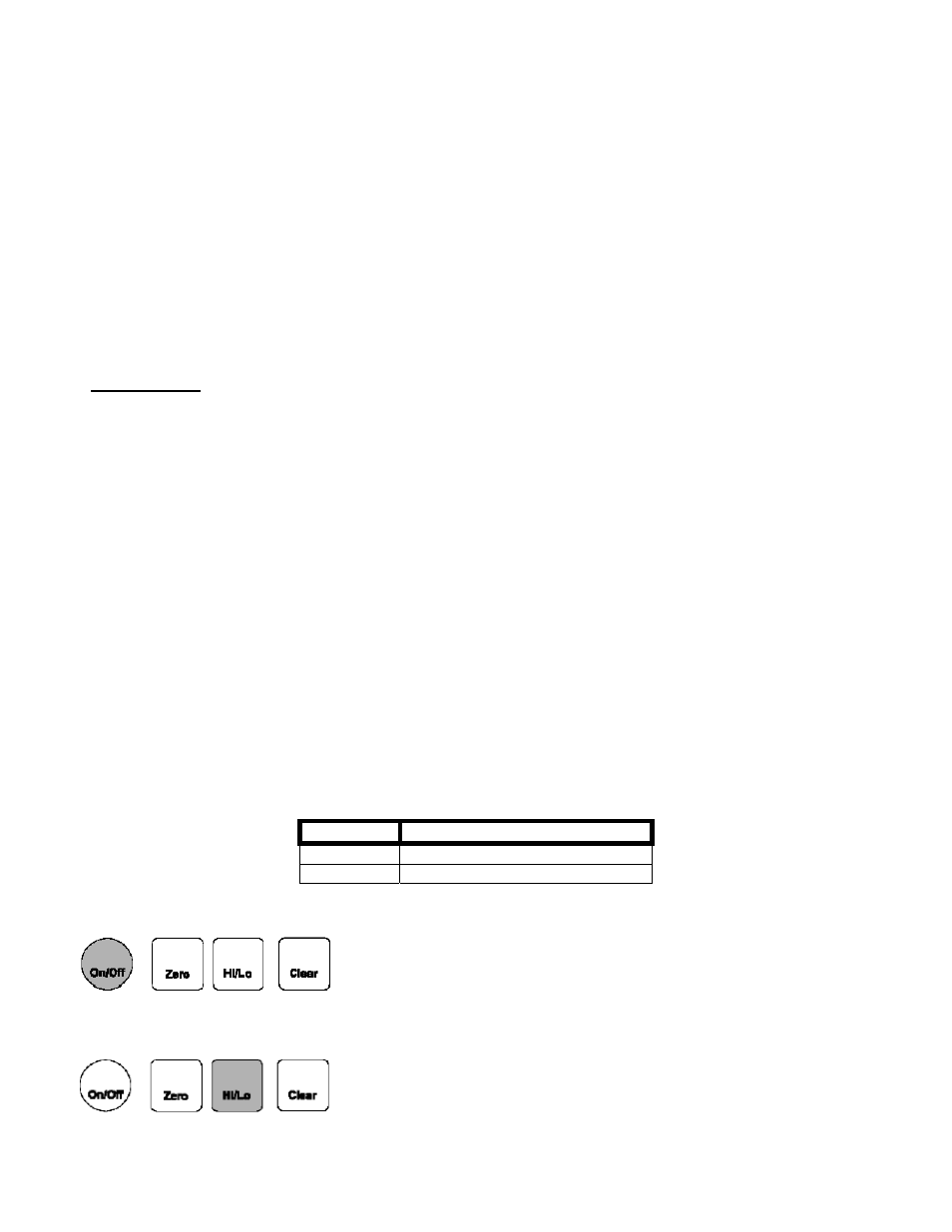
Push the [On/Off] button to turn the instrument on or off.
As the instrument turns on, every segment on the display is momentarily
lighted. The high/low data values are cleared.
3.5
Zeroing the Display
Hold the [Zero] button until the On/Off Zero Clear the display shows "-0-"
(about 5 seconds).
The instrument will retain this zero value even after the instrument has been turned off.
DPG 100
7
Rev Feb 2001