Rdetail r scale 1 : 4, Mounting on the wall, Figure 4 – Amico Light-Duty Monitor Arm User Manual
Page 8: Figure 5, 8amico accessories inc, H-snptog-1420 x-lma-wal-ada, Lma-__-(_____)
8
Amico Accessories Inc.
SECTION 3: Installation on Mounting Platform
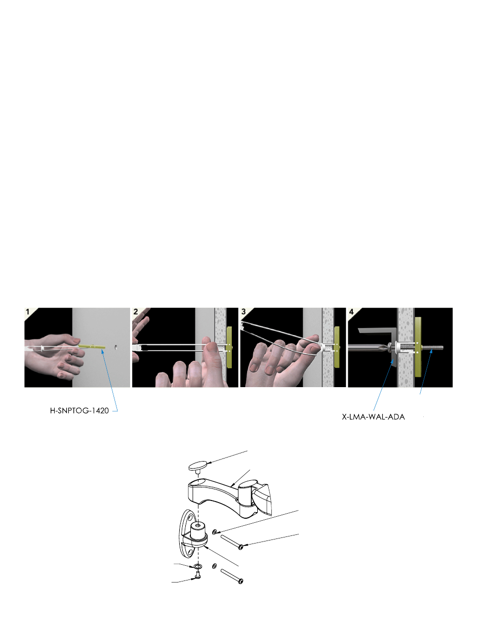
Mounting on the Wall
1. Drill a 1/2" (12.7 mm) hole at the desired mounting height. Hold metal channel of H-SNPTOG-1420 flat alongside
plastic straps and slide channel through hole. Minimum clearance behind the wall is 1-7/8" (47.6 mm). See
Figure 4.1.
2. Hold ends of straps between thumb and forefinger and pull toward you until channel rests flush behind the wall.
Slide plastic cap along straps with other hand until flange of cap is flush with the wall. See Figure 4.2.
3. Snap straps at wall by pushing side to side and snapping off straps level with flange of cap. See Figure 4.3.
*** Repeat steps 1 to 3 for the other hole on X-LMA-WAL-ADA ***
4. Place X-LMA-WAL-ADA over flange. Insert H-PHMS-1420-212 with #3 Philips head screwdriver and tighten until
flush against item, then stop, as shown in Figure 4.4.
5. Assemble LMA to X-LMA-WAL-ADA by placing LMA onto X-LMA-WAL-ADA and securing with the screw through
washer, X-LMA-WAL-ADA, LMA, and into cap, using #3 Philips head screwdriver (as shown in Figure 5).
*** Repeat 1 to 3 for the other hole on X-LMA-WAL-ADA***
www.amico.com
PROJECTION
DATE:
DATE:
NTS
DRAWING NO:
OF
SHT.
CHECKED BY:
DRAWN BY:
SCALE:
PART NO:
DESCRIPTION:
H-PHMS-1420-212
Figure 4
R
DETAIL R
SCALE 1 : 4
LMA-__-(_____)-__
CAP
(PART OF X-LMA-01-01)
WASHER
(PART OF X-LMA-01-01)
SCREW
(PART OF X-LMA-01-01)
X-LMA-WAL-ADA
2 X WASHER
(PART OF X-LMA-WAL-ADA)
2 X H-PHMS-1420-212
CUSTOMER
PROJECT 394
FOR USE WITH: LMA-__-WAL-__
Drill a 1/2" hole at desired height. Hold metal channel of H-SNPTOG-1420 flat alongside plastic straps and slide channel through hole.
1.
Minimum clearance behind wall: 1-7/8".
Hold ends of straps between thumb and forefinger and pull toward you until channel rests flush behind wall.
2.
Slide plastic cap along straps with other hand until flange of cap is flush with wall.
Snap straps at wall by pushing side to side, snapping off straps level with flange of cap.
3.
*** Repeat 1 to 3 for the other hole on X-LMA-WAL-ADA***
Place X-LMA-WAL-ADA over flange. Insert H-PHMS-1420-212 and tighten until flush against item, then stop.
4.
Insert LMA-__-(_____)-__ into X-LMA-WAL-ADA and tighten with cap, washer and screw provided.
5.
H-SNPTOG-1420
X-LMA-WAL-ADA
5
4
LMA ASSEMBLY
www.amico.com
PROJECTION
20140526-E2900
LMA-__-(_____)-__
LMA ASSEMBLY
85 Fulton Way
Richmond Hill, Ontario
L4B 2N4, Canada
Toll Free: 1.877.264.2697 (T)
Tel: (905) 763.7778
Fax: (905) 763.8587
2014-06-10
EC
2014-05-26
JT
DATE:
DATE:
THIS PRINT IS PROPERTY OF AMICO ACCESSORIES
AND IS LOANED IN CONFIDENCE SUBJECT TO RETURN
UPON REQUEST AND WITH THE UNDERSTANDING THAT
NO COPIES ARE TO BE MADE WITHOUT THE CONSENT
OF AMICO ACCESSORIES
ALL RIGHTS TO DESIGN OR INVENTION ARE RESERVED
PRIVATE AND CONFIDENTIAL
11
9
NTS
DRAWING NO:
OF
SHT.
CHECKED BY:
DRAWN BY:
SCALE:
PART NO:
DESCRIPTION:
Figure 5