Test unfold – Great Plains NP4000 Applicators User Manual
Page 15
Test Installation
Great Plains Manufacturing, Inc.
15
2012-08-30
401-828M
Test Unfold
Move the applicator to field conditions for the remaining
tests.
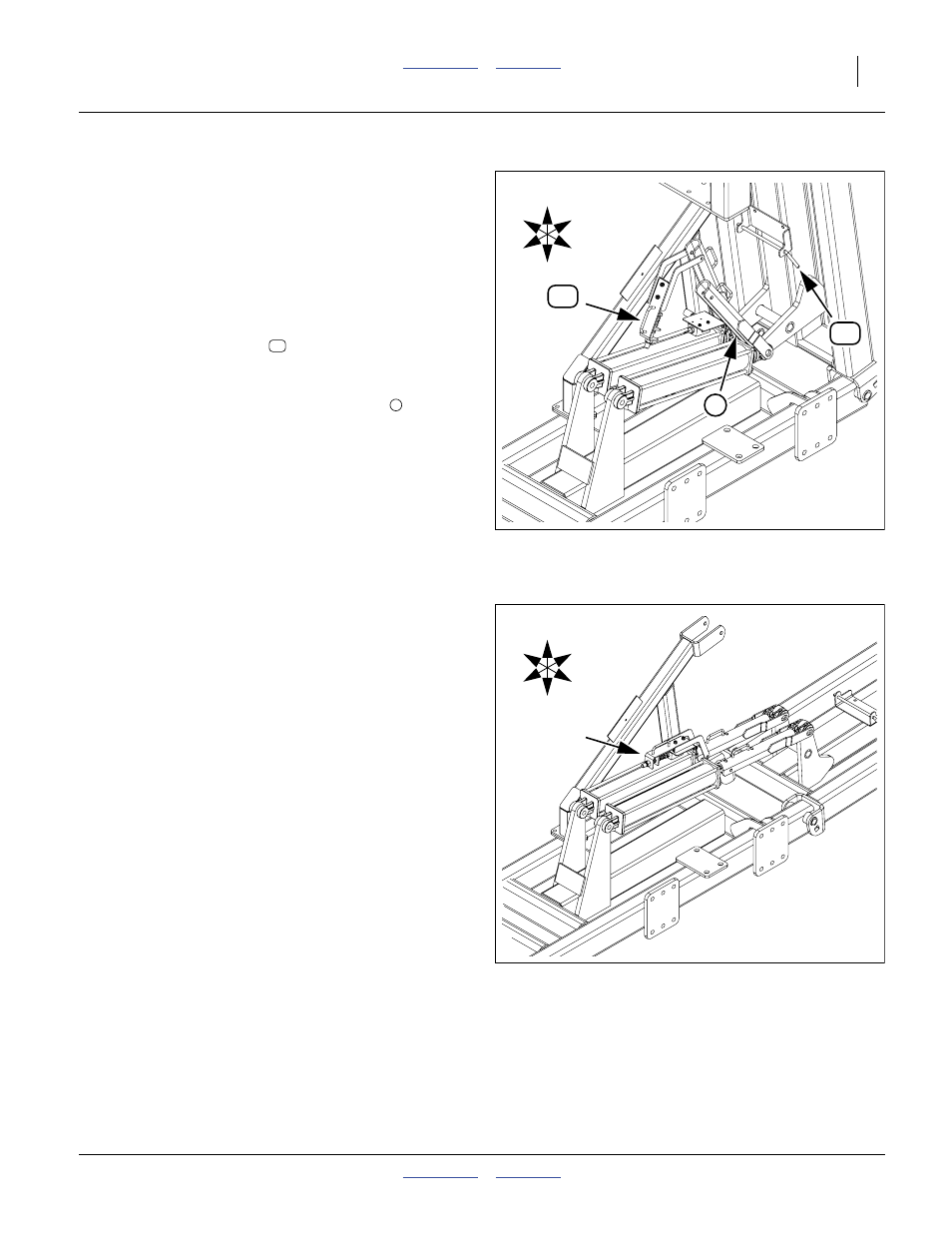
Refer to Figure 23 and Figure 24
79. Remove the wing lock pins (not shown, see
Operator manual).
80. Extend the lift-assist circuit to free the lift lock
channels.
81. At each wing, un-pin both cylinder stop channels.
82. Set the spring plunger
so that the spring-loaded
bolt rests on the cylinder, inboard of the stroke
control valve.
83. Rest the standard cylinder stop channel
the end of the cylinder.
84. Extend the fold circuit to unfold the wings.
The channel and spring plunger fall into place,
causing the inner wing unfold to stop just above
wings-level, followed by outer wing unfold.
85. Set the fold circuit to Neutral. Inspect the inner wing
elevation, and the engagement of the spring-loaded
bolt with the stroke control valve actuator.
If the inner wings stopped at or below wings-level,
raise the wings slightly and make adjustments to the
spring plunger assembly.
Note: The spring plunger is used only for initial unfold
from transport configuration. It is disengaged for
field operations. See the updated Operator
manual for details of field operations.
Figure 23
Ready for Unfold
34108
7
U
D
R
L
F
B
7
Figure 24
Initial Unfold Complete
34104
U
D
R
L
F
B