Great Plains NP4000 Applicators User Manual
General information, Related documents, Notations and conventions
Great Plains Manufacturing, Inc.
1
© Copyright 2012
Printed 2012-08-30
401-828M
Nutri-Pro
®
Spring Plunger Update
NP40 and NP4000 Applicators
General Information
These instructions explain how to update the fold locks
on 2-point (semi-mounted) 5-section Nutri-Pro
®
applicators. The kit reduces machine damage risk by
adding a hydraulic limiter for the inner fold cylinders, and
by providing lock channel capture during transport.
One kit updates one applicator.
These instructions apply to an installation of:
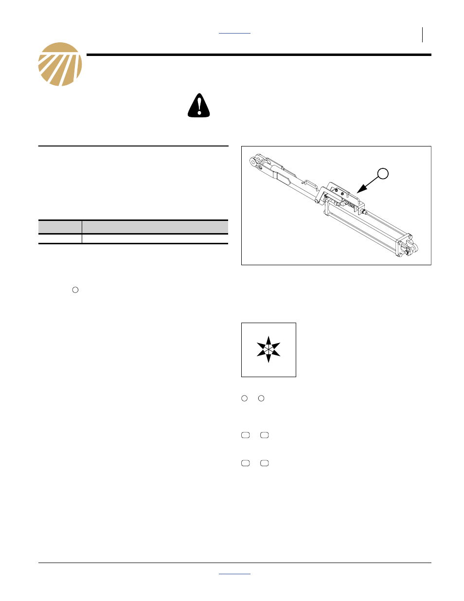
Refer to Figure 1
This kit is not required for pull-type applicators, or any
applicators manufactured in 2012 or later. If the
applicator in question already has the spring plunger
assembly
on the lock channel, and a stroke control
valve on the cylinder, this kit is not required.
Some applicators, which do require the spring plunger
update, may not require all of the parts in this kit.
Related Documents
Have the following manuals available for implement
operations and parts identification.
Notations and Conventions
Call-Outs
When you see this symbol, the subsequent instructions
and warnings are serious - follow without exception.
Your life and the lives of others depend on it!
Kit
Kit Description
401-827A
NP4000 UPDATE KIT. SPRG PLG
Figure 1
Spring Plunger Components
34094
1
407-313M
NP40L Operator Manual
407-313P
NP40 Parts Manual
407-502M
NP40A Operator Manual
407-776M
NP4000 Operator Manual
407-776P
NP4000 Parts Manual
“Left” and “Right” are facing in the
direction of machine travel. An
orientation rose in the line art
illustrations shows the directions of
Up, Back, Left, Down, Front and Right.
to
Single-digit callouts identify components in
the currently referenced Figure. These
numbers may be reused for different items
from page to page.
to
Two-digit callouts in the range 11 to 22
reference existing parts from the list on
page 20.
to
Two-digit callouts in the range 51 to 86
reference new parts from the lists on page 19.
U
D
F
B
L
R
1
9
Document Outline
- NP40 and NP4000 Applicators
- General Information
- Pre-Assembly Preparation
- Install Lower Stiffener Bars
- Remove Stop Rods
- Install Upper Stiffener Bars
- Paint Plates and/or Cuts
- Install Lock Channel Holders
- Replace Aft Cylinder Stops
- Install Mounting Plates
- Assemble LH Valve
- Update Left Hydraulics
- Update Right Hydraulics
- Assemble RH Valve
- Test Installation
- Appendix