Depth stop & angle gauge – Great Plains 3000TM Predelivery Manual User Manual
Page 20
16
1800-3000TM
Great Plains Manufacturing, Inc.
586-536Q
03/19/2014
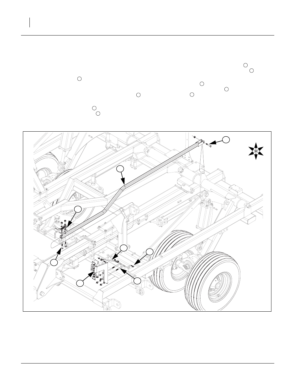
Depth Stop & Angle Gauge
Note: See machine layout drawings in Appendix for
proper gang gauge placement for each model.
58. Slide depth stop tube
from rear of machine under
left wing stop through square hole on depth control
bracket on center wing brace. Align rear holes over
lever on torque tube, secure with 1/2 x 3 hex bolt
,
1/2 top lock nut.
59. Fasten depth stop assembly
on top of depth stop
tube with 1/2 x 2 1/2 hex bolts
, 1/2 lock washers
and nuts.
60. Attach angle gauge bracket assembly
to front of
center frame with 1/2 x 3 1/32 x 6 u-bolts
, 1/2 lock
washers and 1/2 nuts.
61. Attach gauge link
to ear on front of center frame
and gauge bracket assembly
, secure with 3/8 x 1
1/4 hex bolts
and 3/8 top lock nuts.
62. Bolt may be tightened to specs, See “Torque Values
1
2
3
4
5
6
7
5
8
Figure 17
Depth Stop & Angle Gauge
42414
U
D
F
B
L
R
8
5
6
4
3
1
2
7