Assembly, Center brace bar, Valve brackets & valves – Great Plains 3000TM Predelivery Manual User Manual
Page 12: Center brace bar valve brackets & valves
586-536Q
03/19/2014
8
1800-3000TM
Great Plains Manufacturing, Inc.
Assembly
Center Brace Bar
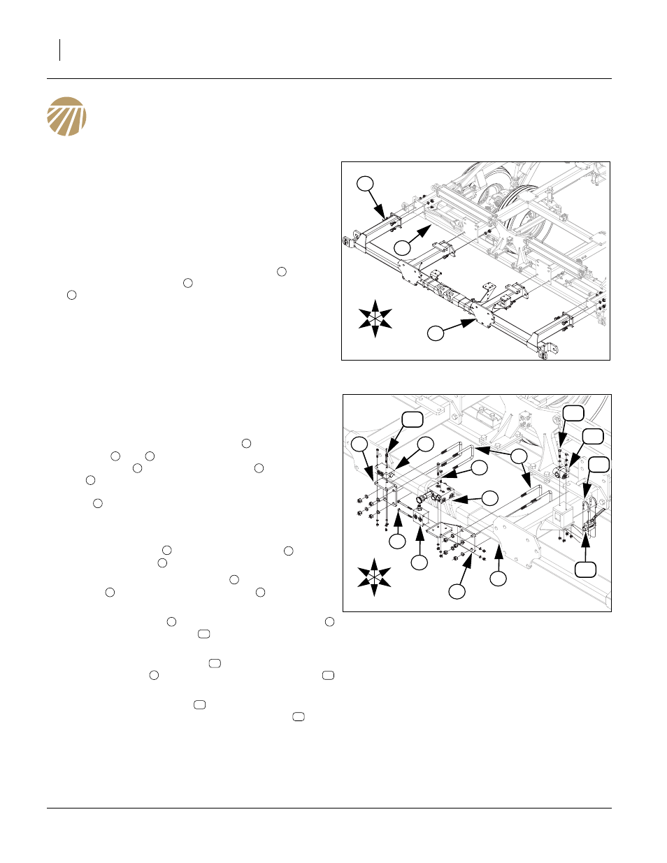
Refer to Figure 5
Note: The center brace bar, front trusses, level bar and hitch
may need to be installed on truck so machine may be
pulled off side of truck. The bolt kit needed for assem-
bling the rest of machine will be shipped in a bag tied to
front of center frame. The center will be shipped partial-
ly pre-assembled. See “Parts Manual” for part numbers
and description of parts.
17. Align holes in plates of the center brace bar
with holes
on front of center frame
, secure with 3/4 x 2 hex bolts
, 3/4 lock washers and 3/4 nuts.
18. Bolts may be tightened to specs, See “Torque Values
Valve Brackets & Valves
Refer to Figure 6
Note: Bolts needed in these next steps will be bolted on parts
or located in a bag on front of center frame.
19. Remove the 1/2 x 3 1/32 x 6 u-bolts
from the valve
brackets
and
, Attach bypass and counterbalance
valve bracket
and lock valve bracket
to center brace
bar
in proper locations, shown, See “Valve Brackets
& Hoses” on page 9, with the same 1/2 x 3 1/32 x 6 u-
bolts
, 1/2 lock washers and 1/2 nuts.
20. Be sure hoses are routed as shown in, See “Valve
Brackets & Hoses” on page 9.
21. Install bypass valve
on top of valve bracket
with 5/16
x 3 Gr. 5 hex bolts
, 5/16 lock washers and 5/16 nuts.
22. Fasten the counter balance valve
to side of valve
bracket
with 5/16 x 4 Gr. 5 hex bolts
, 5/16 lock
washers and 5/16 nuts.
23. Install the lock valve
to the top of the valve bracket
with 1/4 x 2 Gr. 5 hex bolts
, 1/4 lock washers and 1/4
nuts.
24. Fasten the two way fold valve
to top of plate on tube of
center brace bar
with 5/16 x 1 3/8 x 2 3/16 u-bolts
and 5/16 top lock nuts.
25. Attach depth control valve
to top of depth stop bracket
(plunger forward), with 5/16 x 2 Gr. 5 hex bolts
and 5/
16 lock washers.
26. Bolts may be tightened to specs, See “Torque Values
Figure 5
Center Brace Bar
42370
2
3
1
U
D
F
B
L
R
1
2
3
2
1
5
U
D
F
B
L
R
7
4
6
Figure 6
Valve Brackets & Valves
43113
8
9
14
12
11
13
3
10
4
1
2
1
2
3
4
5
1
6
7
1
8
9
2
10
11
3
12
13
14