Level bar, Hitch assembly, Level bar hitch assembly – Great Plains 3000TM Predelivery Manual User Manual
Page 14
10
1800-3000TM
Great Plains Manufacturing, Inc.
586-536Q
03/19/2014
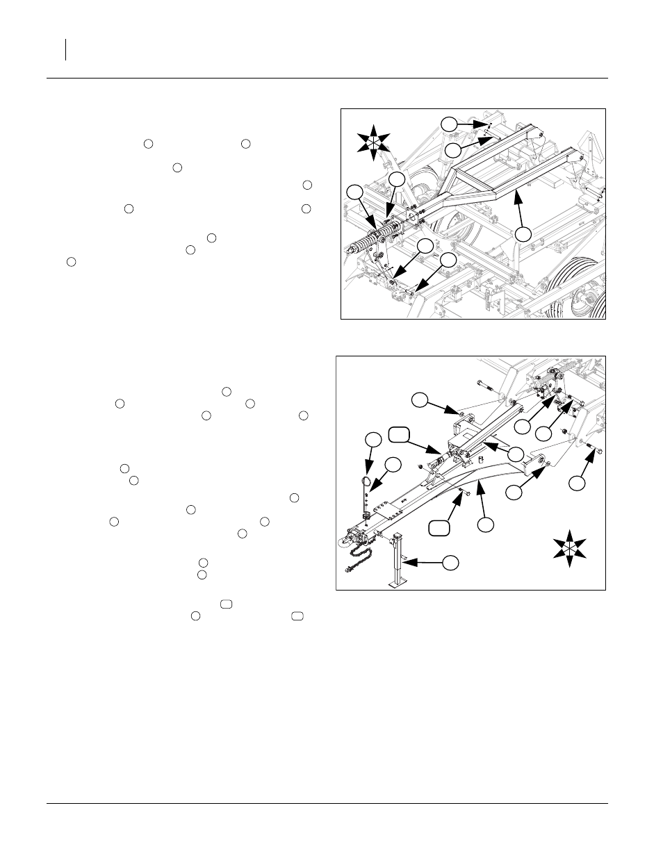
Level Bar
Refer to Figure 9
31. Attach level bar
with 1 x 9 1/2 pin
. Align hole in pin
and holes in collars on outside of torque tube ears, install
3/8 x 2 1/4 Gr. 8 bolts
and 3/8 nylock lock nuts.
32. Align bottom holes on h-bracket spring assembly
with
ears on front of center brace bar, secure with 1 x 3 1/4
usable pins
, 1.5 x 1.0 x.075 machine washers
and
3/16 x 2 cotter pin.
33. Attach front plate of level bar
with rear plate of h-
bracket spring assembly
with 3/4 x 2 Gr. 8 hex bolts
, 3/4 lock washers and 3/4 nuts.
34. Bolts may be tightened to specs, See “Torque Values
Chart” on page 26 and cotter pins bent
Hitch Assembly
Refer to Figure 10
35. Remove the 1 1/4 x 8 Gr. 8 bolts
from the rear of hitch
assembly
. Bolt the hitch assembly
to center frame
with the 1 1/4 x 8 Gr. 8 bolts
, 1 1/4 flat washer
(one
side of uniball to take up space) and 1 1/4 top lock nuts.
Tighten bolts snug, do not torque, as the hitch must pivot
freely.
36. Install jack
on front outside of hitch to support the
front of hitch
for the rest of assembly.
37. Remove 1 1/4 x 8 1/2 Gr. 8 special thread bolt
from
front short level bar tube
. Align holes in rear of level
bar tube
and center hole of h-bracket
. Install the 1
1/4 x 8 1/2 Gr. 8 special thread bolt
from the left side
and secure with 1 1/4 top lock nut.
38. Bolt the spring hose holder
to welded nut on front of
hitch with 1/2 x 1 Gr. 5 bolt
, 1/2 flat washer and 1/2
lock washer.
39. The front of the level turnbuckle
may need attached
to ears on hitch assembly
with 1 x 6 hex bolt
and 1
top lock nut
40. Bolts may be tightened to specs, See “Torque Values
Figure 9
Level Bar
42389
2
6
5
4
1
3
U
D
F
B
L
R
7
1
2
3
4
5
6
1
4
7
Figure 10
Hitch
42388
3
4
1
6
2
8
9
7
5
U
D
F
B
L
R
3
10
11
2
1
1
2
3
4
1
5
6
6
7
5
8
9
10
1
11