Install row extensions – Great Plains FH6800HD Operator Manual User Manual
Page 43
Great Plains Manufacturing, Inc.
Appendix B - Initial Setup
39
04/28/2014
564-070M
Install Row Extensions
Refer to Figure 27 (depicting 4.5ft drags)
A complete kit of 4 bar drag extensions may include a
combination of up to three different widths of drag
assemblies:
564-042L 4 1/2 FT 4 ROW DRAG EXT
564-044L 6 FT 4 ROW DRAG EXT
564-046L 7 1/2 FT 4 ROW DRAG EXT
See Pre-Delivery manual for drag identification.
1.
Set a drag extension (
,
or
) that is the same
width as an existing 12 row drag on the implement.
2.
Remove and save two sets of bolts and nuts from the
drag extension:
803-019C NUT LOCK 1/2-13 PLT
802-091C HHCS 1/2-13X1 1/2 GR5
3.
Align the pull tabs of the extension under the trailing
tabs of the rear-most drag bar. Make sure that the
tooth angle plates
are in the same orientation on
the drag extension as on the main drag. See
Figure 21
on page 37 for details on tooth angle.
4.
Secure pull tabs with bolts
and nuts
.
5.
Repeat step 1 through step 4 for all drag sections.
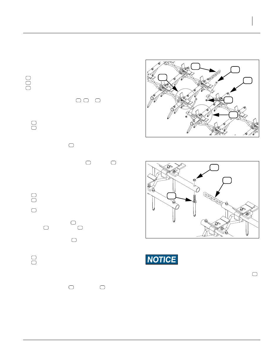
Refer to Figure 28
Move linking chains starting with the center wing.
6.
At bar 12 of the linked drags, remove the teeth
803-342C NUT HEX TOP LOCK 1/2-13 PLT
891-238C HARROW TOOTH - 8 1/2" DIAMOND
securing the linking chain
564-092D CHAIN 5/16 HIGH TEST 8 LINKS
between the drag sections.
7.
Re-install the teeth
at row 12 without the
chain
. Tighten nuts
only to Grade 2 torque
specification, to avoid crushing the tubes.
8.
Re-install the chain
between the same drag sec-
tions at row 16.
9.
To make a chain connection, remove the end set of:
803-342C NUT HEX TOP LOCK 1/2-13 PLT
891-238C HARROW TOOTH - 8 1/2" DIAMOND
10. Insert an end link of the chain in the trailing tube. On
one end, twist the chain
1
⁄
4
turn to align the end link
with the tube hole.
11. Reinstall the tooth
. Tighten nut
only to Grade 2
torque specification, to avoid crushing tube.
12. Repeat step 6 through step 11 for all other drag sec-
tions with linking chains. Some configurations have
only center wing linking chains.
Figure 27
Disconnect Trailing Chain
31772
14
64
41
52
38
38
14
16
18
14
16
18
64
52
38
Machine Damage Risk:
Do NOT link drag sections from wing to wing. The chains
are not long enough to accommodate the distance required for
wing folding.
Figure 28
Relocate Linking Chain
31771
41
41
71
96
52
64
71
96
41
96
41
71
41
71
96
96
71