Position cylinder rod end – Great Plains Verti-Till Field Update User Manual
Page 13
Great Plains Manufacturing, Inc.
Update Lift Cylinders
13
08/06/2007
596-186M
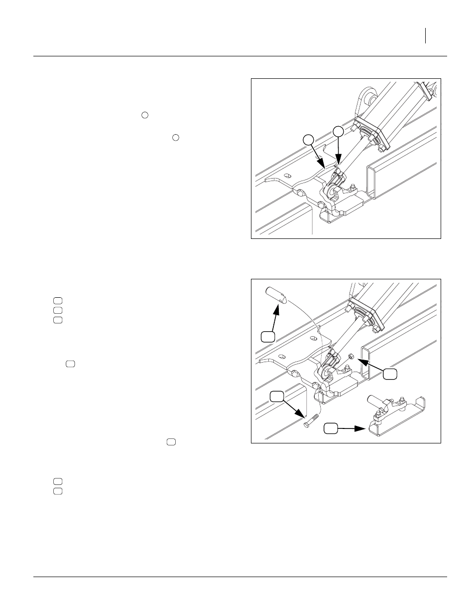
Position Cylinder Rod End
Start with the left side.
Refer to Figure 22
60. Rotate the cylinder clevis
to that the collar bolt is
on top.
61. Extend the clevis onto the arm lug
Refer to Figure 23
62. Select one each set-aside:
596-251D PIN 1 1/4 X 3.94 NON ROT
802-130C HHCS 1/2-13X2 1/2 GR5
803-019C NUT LOCK 1/2-13 PLT
63. Back the clevis off the lug.
64. From the side of the lug opposite the pin keeper
assembly, insert the half-round end of the non-rotate
pin
into the cylinder clevis.
65. Extend the clevis onto the arm lug once more, and
insert the non-rotate pin through the lug, aligning the
flat face of the pin with the forward face of the keeper
lug.
66. Secure the pin with a bolt and nut. Insert the bolt
from the front.
A complete non-rotate assembly
and lug, is shown for reference.
67. If the cylinder rod is sufficiently extended, select one
each:
596-163H CYL LOCK CHANNEL 2 X 9 1/2
805-152C BENT PIN 3/8 X 2 1/2 USE W/COT
and install the lock on the cylinder.
68. Tighten the JIC fittings on the cylinder base ends.
Leave the rod ends loose for later bleeding.
69. Repeat step 60 through step 68 for the right side of
the implement.
Figure 22
Cylinder Rod End to Lug
27053
1
2
2
Figure 23
Install Non-Rotate Pin
27054