Install press wheel assemblies, Engage ground drive spring, Rl f b – Great Plains YP825A3P Operator Manual User Manual
Page 115
Great Plains Manufacturing, Inc.
Appendix B - Pre-Delivery
111
2013-05-28
401-652M
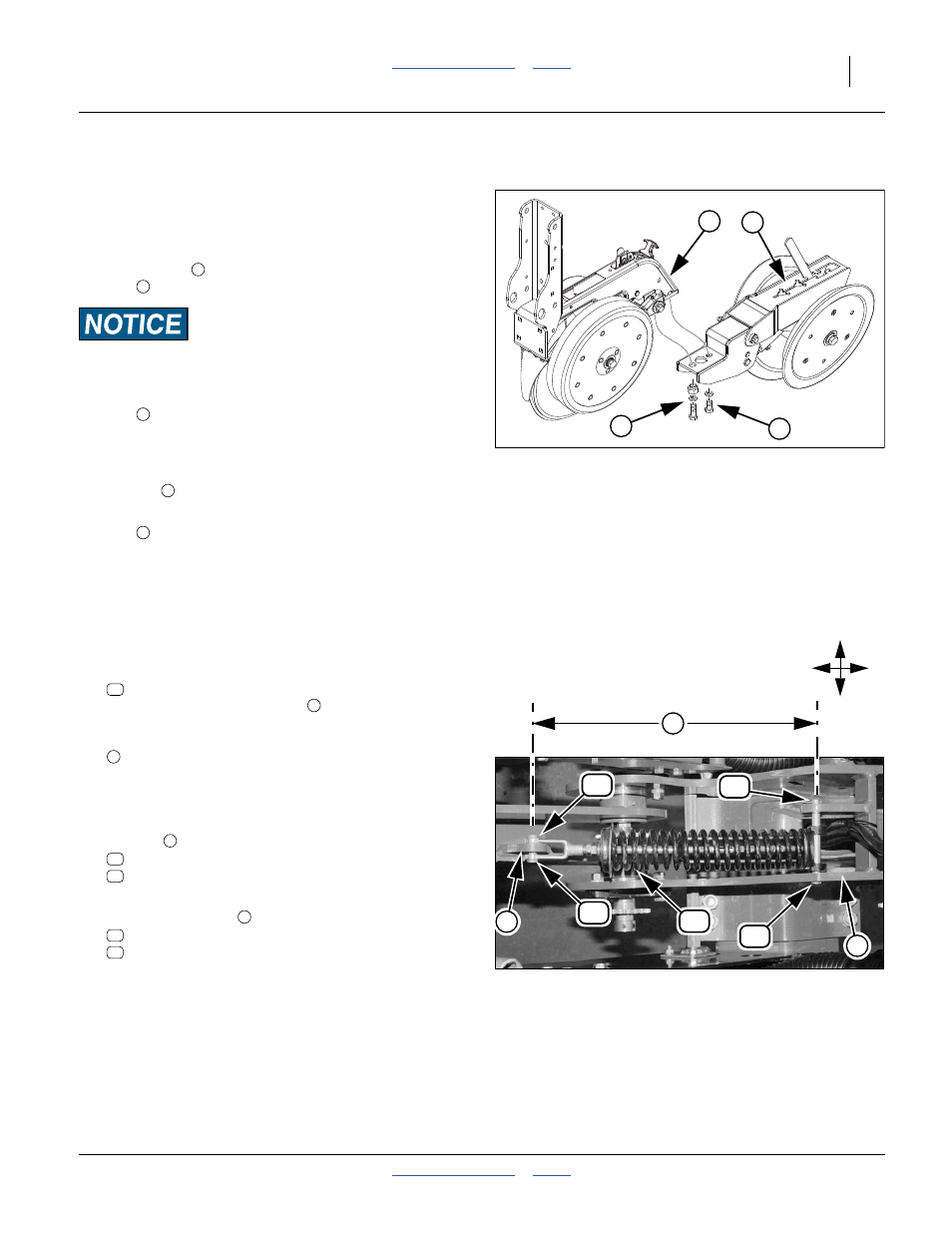
Install Press Wheel Assemblies
To meet highway clearance requirements, press wheel
arms and wheels may not be factory-installed.
Refer to Figure 96
4.
Remove and save the
1
⁄
2
-13x1 inch hex head bolt
and washer
at the back of an incomplete row
unit
.
There are four bolts at this location. Remove only the hex head
bolts. Do not loosen or remove the square head bolts forward.
5.
Remove and save the
1
⁄
2
-13
×
1
1
⁄
2
inch hex head
bolt
, washer, and eccentric adjuster nut.
6.
Align the
1
⁄
2
inch holes in the press wheel assembly
with the
1
⁄
2
-13 tapped holes in the row unit, loosely
assemble with the
1
⁄
2
-13
×
1 inch hex head bolt and
washer
.
7.
Loosely screw in the
1
⁄
2
-13
×
1
1
⁄
2
inch hex head
bolt
, washer, and eccentric adjuster nut. Rotate
the adjuster to visually align the press wheel
assembly with the row unit, and tight the adjust and
both bolts.
Engage Ground Drive Spring
8.
Select one new:
121-763S OPENER SPRING ROD ASSY. SHRT.
Check that the overall length
, from clevis to
trunnion, center-line to center-line, with pin holes
aligned, is:
17
1
⁄
4
inch
±
1
⁄
16
inch (43.7 to 44.0 cm)
9.
Remove and save all pins at clevis and trunnion
ends of spring rod assembly.
10. Secure the clevis end of the spring assembly to the
arm lug
, using one each:
805-127C PIN CLEVIS 1/2 X 1 3/4
and
805-064C PIN COTTER 7/64 X 1 LONG
11. Secure the trunnion end of the spring assembly to
the upper trunnion
, using one each:
805-235C PIN CLEVIS 1/2 X 5 PLATED
and
805-064C PIN COTTER 7/64 X 1 LONG
Figure 96
25AP Press Wheel Assembly
25383
1
2
4
3
2
3
4
2
4
Figure 97
Ground Drive Spring Rod
31038
6
5
R
L
F
B
57
59
58
60
58
7
57
5
59
58
60
58