Great Plains PT1230 AA1080 Operator Manual User Manual
Page 45
43
Section 5 Maintenance and Lubrication
4/12/05
PT1230 Pull-Type Folding Planter 401-069M-B
Great Plains Mfg., Inc.
Replacing Shear Pins
Refer to Figure 5-3.
The cotter pins (1) that connect shafts to the transmission
will shear when an excessive load is put on the shafts.
Infrequent or improper lubrication causes binding of mov-
ing parts within the planter. This binding will cause cotter
pins to shear, preventing major planter damage.
Check for binding by turning drive shaft with all seed hop-
pers installed and seed meters engaged. If drive shaft is
hard to turn, disengage one seed-meter clutch at a time to
find the problem clutch.
Improper shaft alignment also can cause pins to shear.
Refer to Shaft Alignment, this page, to check shaft align-
ment.
When the drill shaft can be turned freely by hand, replace
the sheared cotter pin.
Figure 5-3
Transmission Cotter Pins
Shaft Alignment
Improper shaft alignment can cause cotter pins to shear.
To function properly, the transmission shafts must be
aligned and level. If the planter is consistently shearing
pins, follow these steps to check and adjust the shafts.
1.
Refer to Figure 5-4. Check that transmission-input
shaft (1) and transmission shaft (2) are aligned. Re-
move cotter pin from coupler sleeve. Pull coupler
sleeve back and observe shafts.
IMPORTANT: Replace cotter pins with cotter pins of
the same size. Do not replace with other type pins.
16862
Figure 5-4
Transmission-Input Shaft Alignment
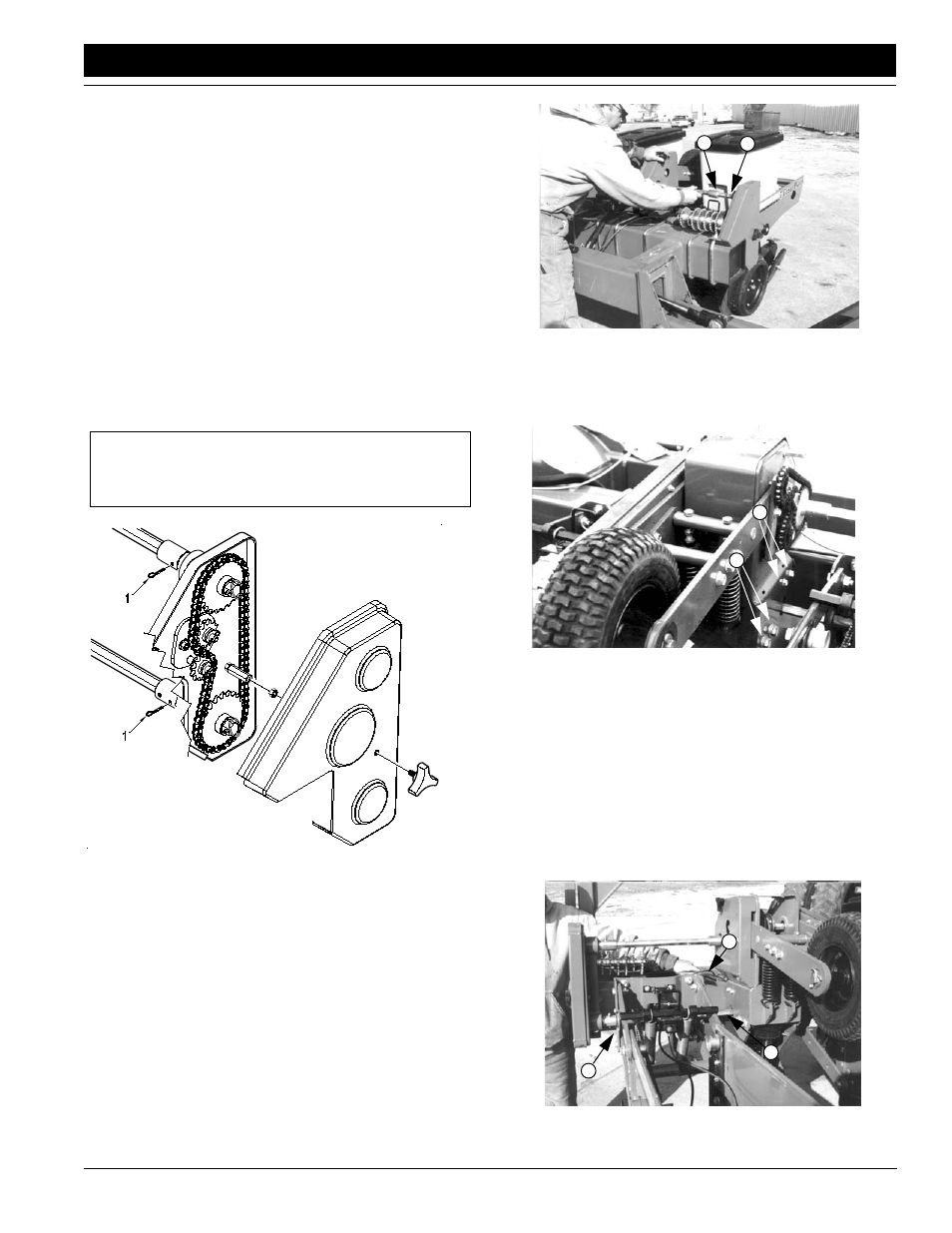
2.
If the shafts are not aligned, adjust contact-drive tow-
er. Loosen mounting bolts (1) on both sides of tower.
Adjust tower position until shafts are aligned.
Figure 5-5
Contact Drive Housing Adjustment
3.
Retighten tower mounting bolts. Slide coupler sleeve
over transmission-input shaft and reinsert cotter pin.
4.
Level transmission-output shaft. Place a straight edge
across the 7-by-7-inch frame tube. Take a measure-
ment from the straight edge (1) down to the top of the
shaft (2). Repeat measurement at each row unit. Mea-
surements must be equal across the planter.
To level the shaft, loosen the shaft hanger bearings (3)
at each row unit. Adjust shaft until measurements are
equal across the planter.
Figure 5-6
Leveling Transmission-Output Shaft
16832
2
1
16849
1
1
16833
1
2
3