Great Plains Min-Till Ladder Kit Assembly Instructions User Manual
Page 3
Great Plains Manufacturing, Inc.
Install Ladder Mounts
3
09/10/2007
195-066M
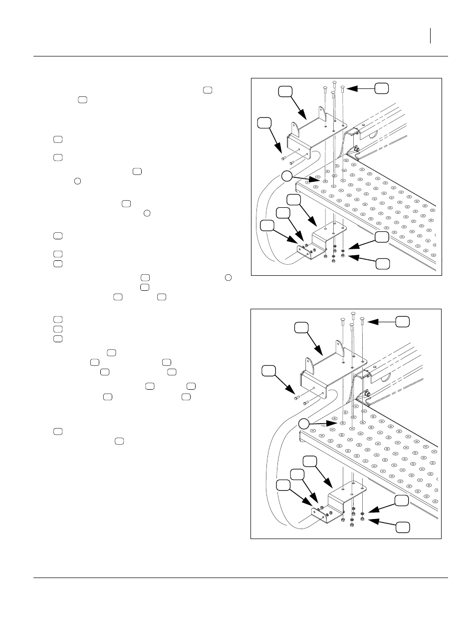
Refer to Figure 3 or Figure 4
Top mount weldments are provided in left-side (
) and
right-side (
) versions and are not interchangeable. All
other parts may be used on either end. Start with the left
wing:
10. Select one:
and four:
802-030C RHSNB 7/16-14X1 3/4 GR5.
11. Position the top mount
over the four walkboard
holes
appropriate for the drill’s configuration (see
12. Insert the four bolts
to loosely hold the top mount
in place on the walkboard
13. Select one:
195-340D LADDER MOUNT BOTTOM PLATE
and four sets of:
804-014C WASHER LOCK 7/16 PLT
803-015C NUT HEX 7/16-14 PLT
14. Position the bottom plate
under the walkboard
and inside the top mount
. Loosely hold it in place
with the washers
and nuts
15. Select two sets of:
802-017C HHCS 3/8-16X1 GR5
804-013C WASHER LOCK SPRING 3/8 PLT
803-068C NUT HEX FLANGE 3/8-16 PLT
16. Insert the bolts
through the side holes in both the
top mount
lock washers
and flange nuts
17. Tighten the four
7
⁄
16
in nuts
, securing
the top mount
Refer to Figure 7 on page 6
18. Selecting one:
in place of mount
, repeat step 10 through step 17
for right wing section.
Figure 3
Small Seeds Mount Location
27055
4
4
Figure 4
Location, No Small Seeds
27036
15