Ngp clutch kit assembly (optional), Universal clutch components – Great Plains CDS-JohnBlue NGP Series Pumps User Manual
Page 19
© 2013 CDS-John Blue Co.
19
NGP Clutch Kit Assembly (optional)
Universal Clutch Components
- Assemble as shown in the first schematic figure, and ensure that the clutch yoke
21
is installed against
the clutch jaw
19
according to the schematic for each assembly (either tight or with a 5/16” gap).
- It may be necessary to loosen the set screws on the pump’s stroke adjustment pointer to slide the
main shaft over to allow clutch spacer
4
to fit correctly. Be sure to re-tighten the set screws.
- Grease all fittings
3
daily during seasonal usage.
Manual Clutch: NGP-xxxx-050
Conversion Kit # 115670
- Assemble as shown in the second schematic figure, and ensure that the shift rod
23
and pin
assembly
34-38
are aligned with throw out cam
29
so that the clutch is smoothly engaged/disengaged.
- Place one end of the torsion spring
27
over the 5/16” x 1-1/2” bolt
57
after assembling the bolts to the
mounting plate
27
and the other end against the ear on the throw out bracket
28
.
Electric Clutch: NGP-xxxx-058
Conversion Kit # 115672
- Assemble as shown in the third schematic figure – be sure to note the required 5/16” gap between the
yoke and clutch jaw when retracted.
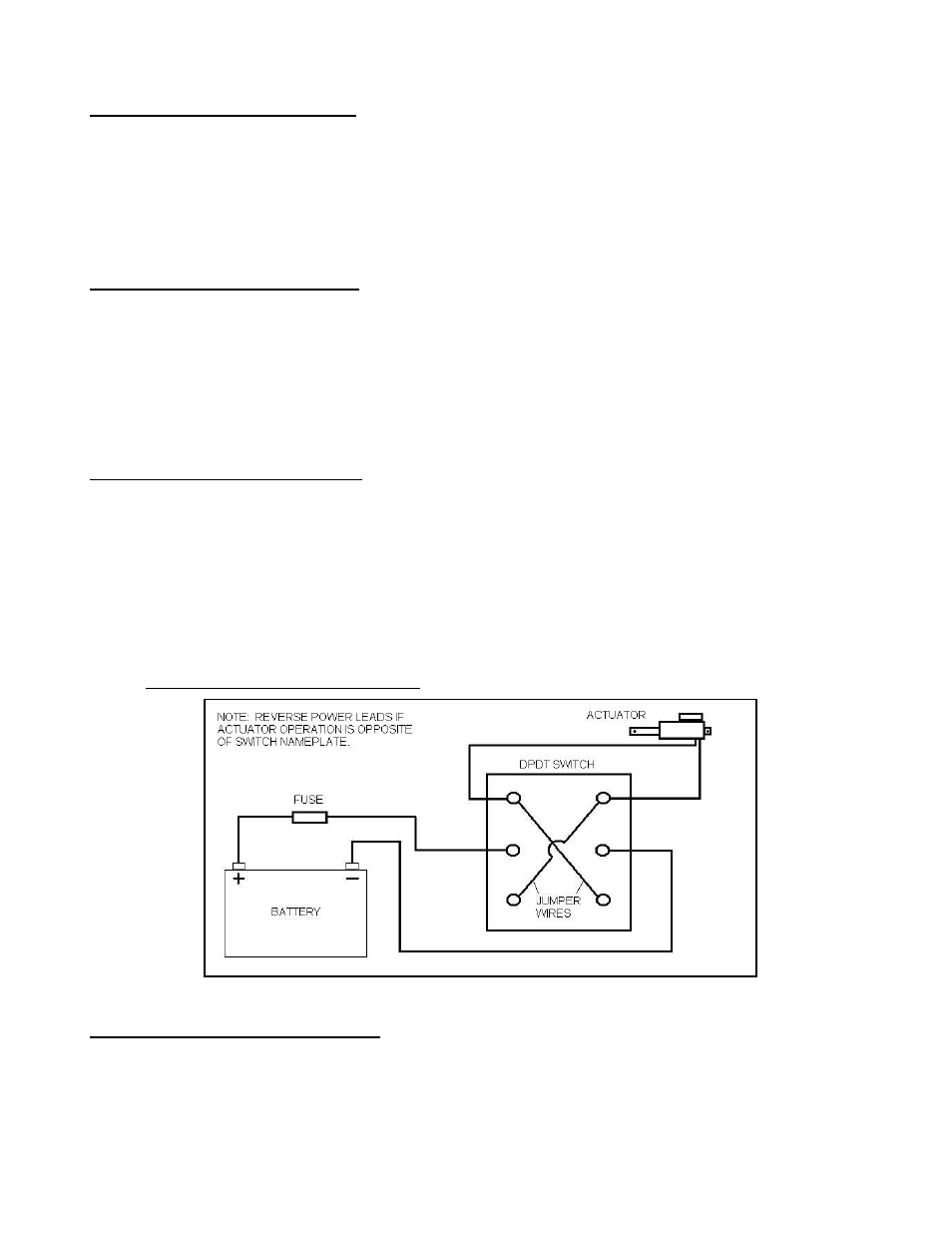
- A double pole / double throw (DPDT) switch must be obtained and wired to the actuator
48
. The switch
should be rated for 10A min., and can be either a sustaining or a momentary centering type.
- A 10 Amp fuse must be installed before the switch – see the diagram below for connecting the
switch and actuator.
Electric Actuator/Switch Wiring Diagram:
Hydraulic Clutch: NGP-xxxx-059
Conversion Kit # 115671
- Assemble as shown in the fourth schematic figure, and ensure that the jam nut
22
is fully threaded onto
the shifter rod
23
.