Great Plains CDS-JohnBlue NGP Series Pumps User Manual
Page 13
© 2013 CDS-John Blue Co.
13
INTERNAL DISASSEMBLY
Reference to the schematic section is recommended prior to disassembly of the internal crankcase components
to familiarize yourself with components. The wet-end components, inboard, and outboard components should
be removed prior to internal disassembly as outlined in previous sections of this manual.
Supporting the piston rod with a wood block, locate the
crosshead pin, which connects the piston rod and connecting
rod and carefully drive pin out with a hammer and punch.
Inspect the connecting rod bushing for damage and replace as
necessary during re-assembly.
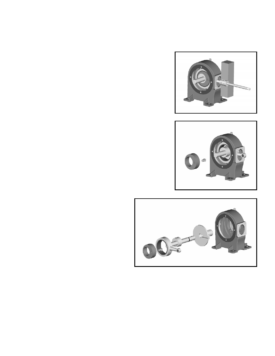
Slide the outer eccentric and eccentric pin out of the crankcase.
The connecting rod can then be removed by carefully sliding it
out the side of the pump at an angle.
The shaft can then be removed as shown with the inner
eccentric still in place.
Note:
Double piston pumps will require the stroke transfer
sleeve to be removed with the shaft exposing the
second piston eccentric and connecting rod for removal.
The stroke setting sleeve is then removed.
The eccentric pins may slide out during any
part of this process and should be
accounted for, single pumps utilize 1,
double pumps utilize 3 [ref schematic].
Examine all components, giving more
attention to ones showing “galling” than to
ones which are undersize, yet smooth.
CRANKCASE RE-ASSEMBLY
All components in the gasket kit should be used during re-assembly.
Reassemble the crankcase in reverse order.
When assembling the shaft, oil the shaft o-ring and carefully insert into stroke setting sleeve.
It is extremely important that all eccentric pins engage appropriate mating slots.
Coat all bolts threads with gasket sealant before installing in crankcase.