Rear stand, Weight package assembly (optional), Rear stand weight package assembly (optional) – Great Plains 1500TM Assembly Manual User Manual
Page 26
22
1200-1500TM
Great Plains Manufacturing, Inc.
586-535Q-ENG
12/12/2013
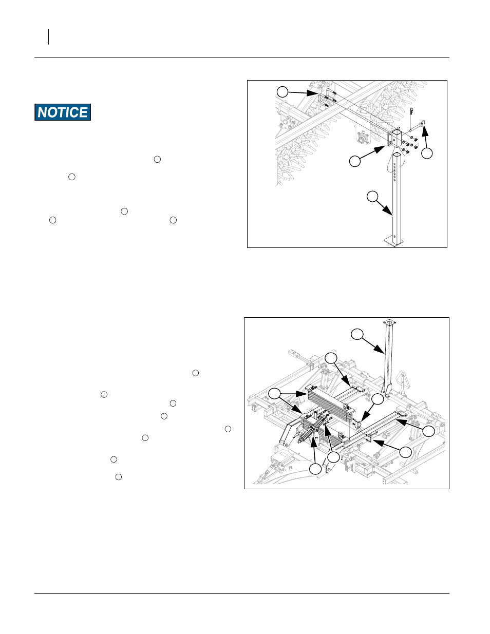
Rear Stand
Refer to Figure 21
If machine is equipped with a rear attachment, be sure you install
the rear jack stand so machine doesn’t tip backwards when
unhooking machine from tractor.
81. Attach the rear stand bracket
to the center of, the
rear tube of the drag frame with 5/8 x 3 1/32 x 4 1/2 u-
bolts
, 5/8 lock washers and 5/8 nuts.
82. Tighten u-bolts specs, See “Torque Values Chart” on
83. Slide the rear stand
through the rear stand bracket
, secure with the 3/4 x 5 1/4 pin
and retainer.
84. Once the options are installed, fold the Turbo Max to
check for clearance and interferences, also watch that
hoses do not get pinched.
Note: Double check that all bolts are tightened to specs,
See “Torque Values Chart” on page 24.Consult the
“Operator’s Manual”, for the first time field adjust-
ments before going to the field.
Weight Package Assembly (Optional)
Refer to Figure 22
Caution: Lower machine until coulters are on ground and
pressure is off leveling system.
Note: Up to 1 set of weights (2 weights) may be used in po-
sitions shown.
85. Start by removing the 3/4 x 2 Gr. 8 bolts
from level
bar assembly.
86. Pivot level bar
up so there will be clearance to set
the 750 pound weight assemblies
into place.
87. Pivot level bar spring assembly
forward.
88. Carefully lower the 750 pound weight assemblies
onto center frame trusses
.
89. Slide rear weights as far forward as possible and install
weight box stops
on inside of trusses as close to
weight as possible (rear weights), secure with 1/2 x 4
1/32 x 5 1/4 u-bolt
, 1/2 lock washers and 1/2 nuts.
90. Torque u-bolts to 85 ft-lbs.
4
Figure 21
Rear Stand
42438
3
1
2
1
2
3
1
4
Figure 22
Weight Package
43105
2
3
6
7
1
4
5
5
1
2
4
3
4
5
6
7