Assembly, Center frame & lift assembly – Great Plains 1500TM Assembly Manual User Manual
Page 12
586-535Q-ENG
12/12/2013
8
1200-1500TM
Great Plains Manufacturing, Inc.
Assembly
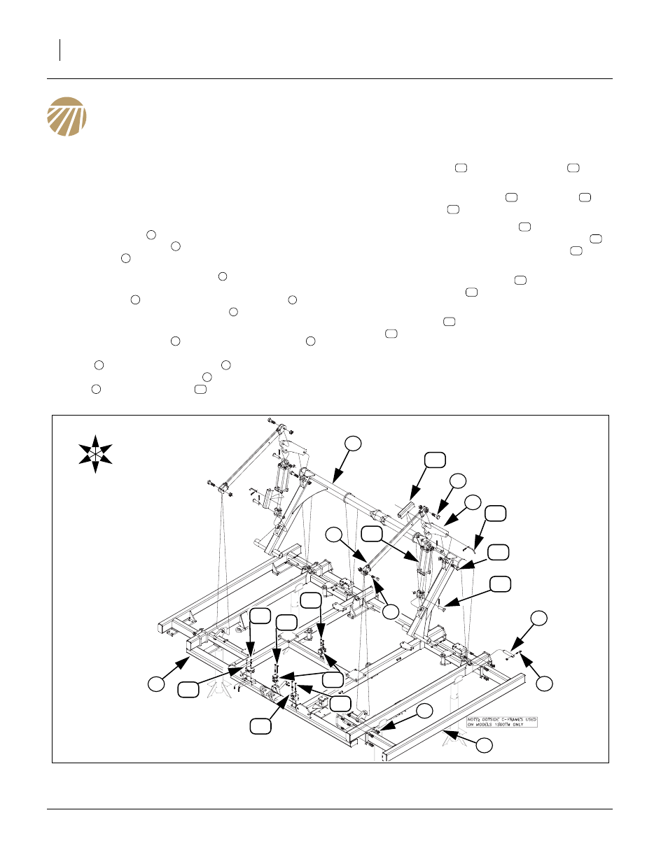
Center Frame & Lift Assembly
Refer to Figure 5
Note: Once the center frame has been uncrated and put
on stands, the rest of components may be
installed. See “Parts Manual” for part numbers
and description of parts.
3.
Attach c-frames
(Model 1500TM only) to both
sides of center frame
, secure with 3/4 x 5 1/32 x 4
1/2 u-bolts
, 3/4 lock washers and 3/4 nuts.
4.
Carefully lower the torque tube
with an overhead
hoist until holes are aligned with the holes on top of
center frame
and secure with 1 1/4 x 7 pins
, 3/8
x 2 1/4 Gr. 8, special thread bolts
and 3/8 top lock
nuts.
5.
Align hole in lift strap
and cylinder mount plate
in proper orientation shown in drawing. Secure lift
strap
with 1 x 3 1/2 hex bolts
and 1 lock nuts,
rear of cylinder mount plate
to plates of torque
tube
with 1 x 4 hex bolt
and 1 lock nut.
6.
Install the cylinders
using 1 x 3 1/8 pins
, 1.5 x
1.0 x.075 machine washers and 3/16 x 2 cotter pin.
7.
Install cylinder transport locks
to cylinders
using 3/8 x 3 pins
and clip pins.
8.
Install the two, double block tees
in orientation
and positions shown with 5/16 x 2 1/2 hex bolts
,
5/16 lock washers (rear), 5/16 x 4 hex bolts
, 5/16
lock washers and 5/16 nuts (front).
9.
Install the counterbalance valve
to front tube with
5/16 x 3 1/2 hex bolts
, 5/16 lock washers and 5/
16 nuts.
10. Attach lock valve
to front tube with 1/4 x 2 hex
bolts
, 1/4 lock washers and 1/4 nuts.
11. Tighten all bolts with lock nuts snug, but do not
torque. The rest of the bolts may be tightened to
specs, See “Torque Values Chart” on page 24.
1
2
3
4
2
5
6
7
8
7
9
8
4
10
11
12
13
11
14
15
16
17
18
19
20
21
Figure 5
Center Frame & Lift Assembly
42980
12
18
5
U
D
F
B
L
R
1
3
2
4
11
6
8
7
20
13
14
15
19
16
9
9
10
21 17