Center transport, Trusses & level bar, Center transport trusses & level bar – Great Plains 1500TM Assembly Manual User Manual
Page 13
Great Plains Manufacturing, Inc.
Assembly
9
12/12/2013
586-535Q-ENG
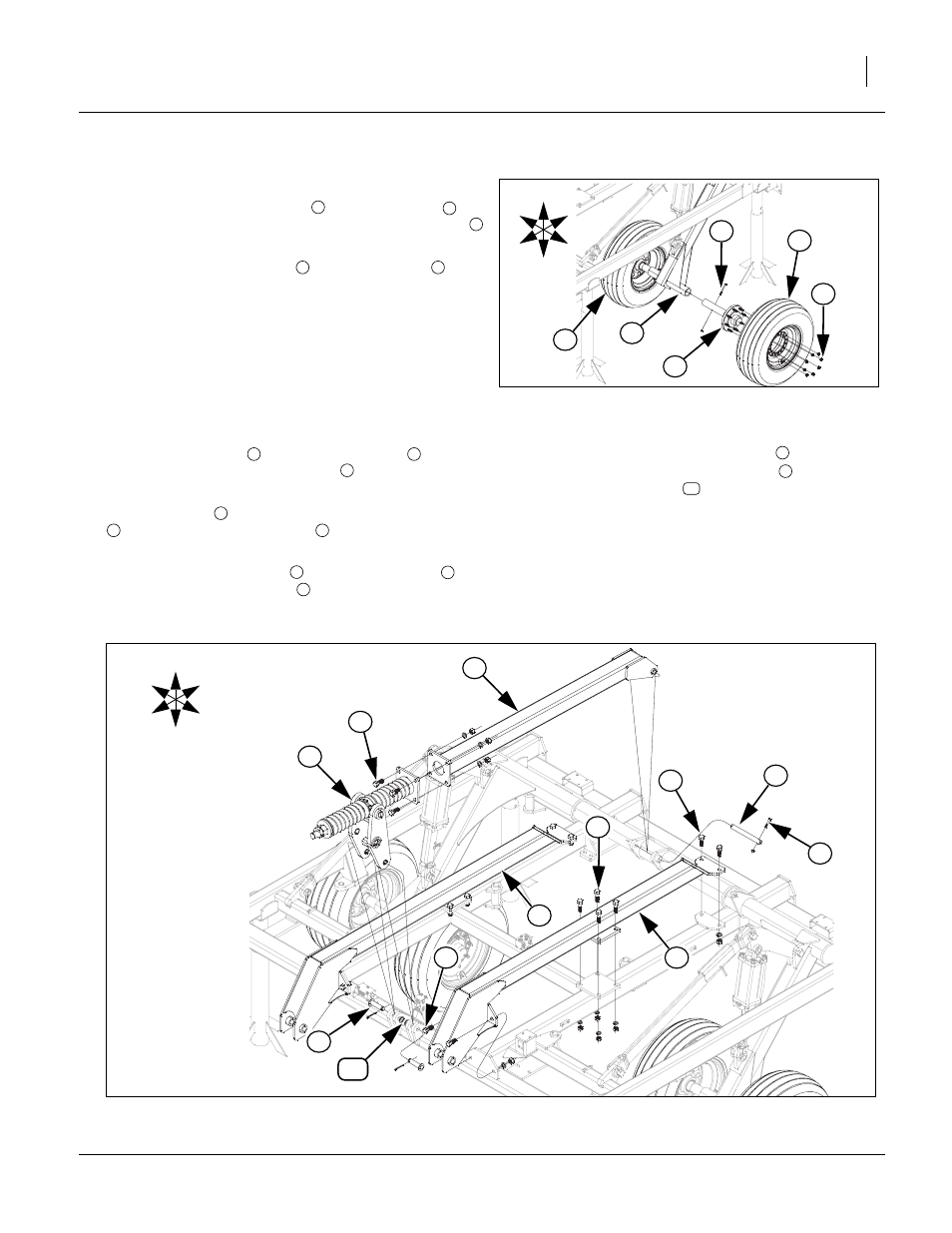
Center Transport
12. Slide hub/spindle assemblies
into torque tube
and
align holes. Secure with 5/16 x 3 1/2, Gr. 8 hex bolts
and 5/16 top lock nut.
13. Attach tire/wheel assembly
with 5/8 lug nuts
.
14. Tighten all bolts with lock nuts snug, but do not torque.
The rest of the bolts may be tightened to specs, See
“Torque Values Chart” on page 24.
Trusses & Level Bar
Refer to Figure 7
15. Attach hitch trusses
with 3/4 x 2 hex bolt
(front
& rear plates), 3/4 x 2 1/2 hex bolt
(middle plates),
3/4 lock washers and 3/4 nuts.
16. Install level bar
to torque tube with 1 x 9 1/2 pins
, 3/8 x 2 1/4, Gr. 8 hex bolts
and 3/8 nylon lock
nut.
17. Install h-bracket assembly
to front of level bar
with 3/4 x 2, Gr. 8 hex bolts
, 3/4 lock washers and
3/4 nuts.
18. Install bottom of h-bracket assembly
to front of
center frame with 1 x 3 1/4 clevis pin
, 1.5 x 1.00
x.075 machine washer
and 3/16 x 2 cotter pin.
19. Tighten all bolts with lock nuts snug, but do not
torque. The rest of the bolts may be tightened to
specs, See “Torque Values Chart” on page 24.
1
U
D
F
B
L
R
4
Figure 6
Center Transport
42981
3
5
2
4
1
2
3
4
5
1
2
3
4
5
6
7
4
8
7
9
10
U
D
F
B
L
R
5
1
7
4
9
6
2
10
Figure 7
Trusses & Level Bar
42982
1
3
8
2