Install cylinder hoses, Install left cylinder hoses, Left sag and slack – Great Plains NTA2007HD Installation Instructions User Manual
Page 9
Great Plains Mfg., Inc.
Installation Instructions
9
2013-10-16
113-921M
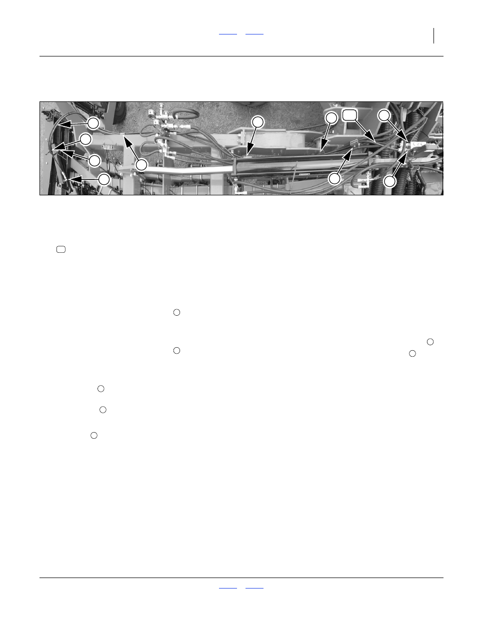
Install Cylinder Hoses
Install Left Cylinder Hoses
Refer to Figure 12 (a composite image depicting the 2013-
kit, which has identical hose routing beyond the cylinder)
40. Select two hoses:
851-106C HH3/8R2 154 9/16FJIC
One with orange tie or “R” tag, and one without.
41. Connect one end of the hose with the orange/R
marking to sequence valve port R.
42. Connect the unmarked hose to sequence valve
port C
43. Route the hoses under the clamp
face of the wing lock lug. Leave clamps lightly snug
at this time, to allow for sag and slack adjustment at
step 47.
44. Route the hoses under the clamp
near the fold cylinder rod end.
45. Route the hoses to the front of the wing, under the
adjustment valve assembly and under the outer
wing clamp
.
46. At the cylinder, connect the orange/R hose to the
elbow fitting
at the rod end.
Connect the unmarked hose to the elbow at the
base end
47. Adjust hose sag and slack per suggestions at right.
48. Tighten all clamps.
Figure 12
Left Cylinder Hose Routing
31345
R
C
1
6
2
3
4
5
7
8
82
Left Sag and Slack:
• Allow just enough sag at the wing pivot so that the
hose is near, but no lower than the wing pivot pin
.
• Where the hoses naturally cross each other
at the
cylinder, secure a cable tie.
• Add a second tie approximately 40 cm (16 inches)
away, to bundle the hoses.
• Create enough slack at this location for a loop no
higher than the eyebolt on the gauge wheel. The rod
end hose must follow the rod end of the cylinder as it
swings out and toward the rear during marker
extension.
• Balance remaining slack at the adjustment valves and
at the sequence valve.
• Check that all slack is clear of moving parts.
82
1
2