Appendix, Hydraulic connector identification – Great Plains NTA2007HD Installation Instructions User Manual
Page 16
16
2014+ Single Fold Marker
Great Plains Mfg., Inc.
113-921M
2013-10-16
Appendix
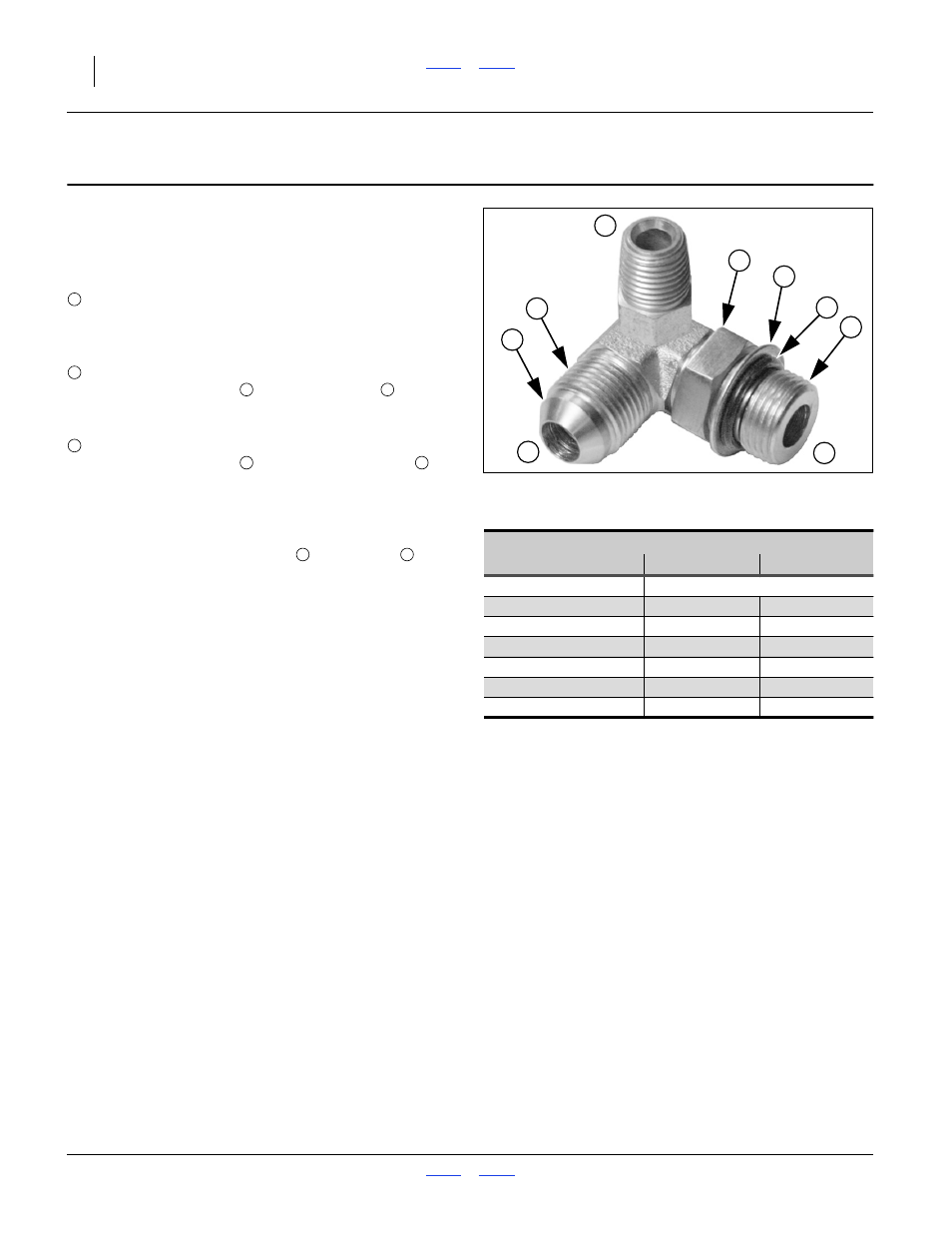
Hydraulic Connector Identification
Refer to Figure 19 (a hypothetical fitting)
Leave any protective caps in place until immediately prior
to making a connection.
NPT - National Pipe Thread
Note tapered threads, no cone/flare, and no O-ring.
Apply liquid pipe sealant for hydraulic applications
(do not use tape sealant, which can foul filters).
JIC - Joint Industry Conference (SAE J514)
Note straight threads
and the 37
° cone on
“M” fittings (or 37
° flare on “F” fittings). Use no
sealants (tape or liquid) on JIC fittings.
ORB - O-Ring Boss (SAE J514)
Note straight threads
and elastomer O-Ring
.
Prior to installation, to prevent abrasion during
tightening, lubricate O-Ring with clean hydraulic fluid.
Use no sealants (tape or liquid) on JIC fittings.
ORB fittings that need orientation, such as the ell
depicted, also have a washer
and jam nut
(“adjustable thread port stud”). Back jam nut away
from washer. Thread fitting into receptacle until
O-Ring contacts seat. Unscrew fitting to desired
orientation. Tighten jam nut to torque specification.
2
5
4
9
8
7
5
3
Figure 19
Hydraulic Connector ID
31282
Fittings Torque Values
Fitting
Ft-Lbs
N-m
1
⁄
4
NPT
1.5-3.0 turns past finger tight
9
⁄
16
JIC
18-20
24-27
9
⁄
16
ORB w/jam nut
12-16
16-22
9
⁄
16
ORB straight
18-24
24-32
3
⁄
4
JIC
27-39
37-53
3
⁄
4
ORB w/jam nut
20-30
27-41
3
⁄
4
ORB straight
27-43
37-58
1
1
2
4
5
3
5
7
8
9