Install arm mechanisms, Install first stage arms, Connect cylinder rods – Great Plains YP925TD Assembly Instructions User Manual
Page 15
Great Plains Mfg., Inc.
Installation Instructions
15
2012-22-03
113-870M
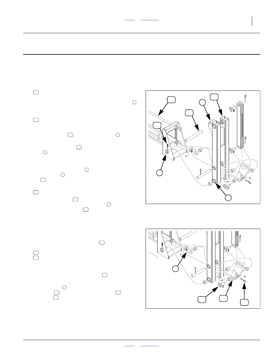
Install Arm Mechanisms
Install First Stage Arms
If the first stage arms are already installed, continue at
“Connect Cylinder Rods”.
Refer to Figure 18
74. Select one new:
113-437H 1ST STAGE ARM WELDMENT or
113-517H 1ST STAGE ARM WMNT
Note that the arm weldment has a stop weldment
on one end, and protruding to one side.
75. Select one new:
113-439D 1ST STAGE MOUNTING PIN
Note that the pin has a hole in one end. When
inserted, this end must be on the same side of the
mount weldment
as the pivot bushing
with the
hole.
76. Orient the arm stage
with the second stage
stop
such that it will be facing toward planter
center with the arm folded (as shown), and facing
up with the arm unfolded.
77. Align the inner pivot tube
of the arm stage with
the arm pivot
on the mount. Insert the pivot
pin
.
78. Select one new:
805-180C PIN ROLL 1/4 X 1 1/2 LG PLT
79. Adjust the pivot pin
position and rotation to align
its hole with the mount bushing hole
. Secure the
pivot pin with the roll pin
.
80. Repeat step 74 through step 79 for the other arm.
Connect Cylinder Rods
Refer to Figure 19
81. At each first stage arm pivot link
, remove and
save one set:
805-060C PIN COTTER 7/32 X 2
113-448H CYL. PIVOT PIN WMNT
Note: It may be necessary to activate the hydraulic
circuit and slightly extend the cylinder rod in order
to obtain tang to pivot link clevis
alignment.
Observe all cautions on page 13.
82. Align the tang
on the rod end with the clevis end
of the link
. Secure with pin weldment
and
cotter pin
. Repeat for other arm.
83. Unfold both marker arms. Set circuit lever to Extend
until one arm is unfolded. Briefly reverse the lever to
Retract until either arm begins moving, then quickly
reverse it to Extend to extend the other arm.
Figure 18
Marker First Stage Arm
29872
36
67
7
34
6
8
33
34
36
33
34
8
36
67
36
67
Figure 19
Cylinder Rod Connection
29872
9
66
42
41
41
66
42
41
41
42
66