Great Plains YP925TD Assembly Instructions User Manual
General information, Related documents, Notations and conventions
Great Plains Mfg., Inc.
Installation Instructions
1
2012-22-03
©Copyright 2012
113-870M
Flat Fold Marker
Single Section YP Planters
General Information
These instructions explain how to install field markers on
a compatible planter.
These instructions apply to an installation of:
One kit includes two markers (left and right), an
automatic sequence valve, all hydraulic hoses and
fittings, and all necessary mounting hardware.
One kit updates one planter.
Related Documents
Have the Operator Manual at hand for planter
movements.
Have the current Parts Manual at hand for parts
identification.
Notations and Conventions
“Left” and “Right” are facing in the
direction of machine travel. An
orientation rose in the line art
illustrations shows the directions of
Left, Right, Front, Back, Up, Down.
Call-Outs
Used with:
When you see this symbol, the subsequent instructions and
warnings are serious - follow without exception.
Your life and the lives of others depend on it!
• YP425A, YP425A3P
• YP625A, YP625A3P, YP625PD/TD
• YP825A, YP825A3P
• YP925TD
Kit
Kit Description
113-836A
4-30 3P PLTR FLAT FOLD MKR
113-837A
4-30 PT PLTR FLAT FOLD MKR
113-838A
6-30 PT PLTR FLAT FOLD MKR
113-839A
6-38-40 8-30 PT PLTR FOLD MKR
113-854A
4-38-40 PT PLTR FLAT FOLD MKR
113-855A
4-38-40 3P PLTR FLAT FOLD MKR
113-857A
4-36 PT PLTR FLAT FOLD MKR
113-858A
4-36 3P PLTR FLAT FOLD MKR
113-859A
6-36 3P PLTR FLAT FOLD MKR
113-860A
6-36 PT PLTR FLAT FOLD MKR
113-861A
6-110 3P PLTR FLAT FOLD MKR
113-862A
6-110 PT PLTR FLAT FOLD MKR
113-863A
9-65 3P PLTR FLAT FOLD MKR
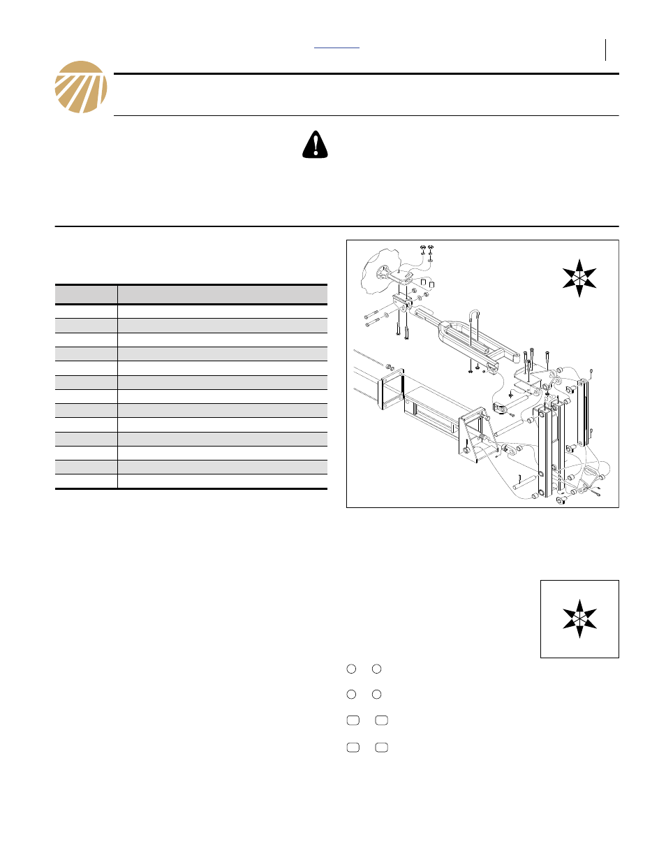
Figure 1
Flat Fold Marker Kit
29872
U
D
F
B
L
R
401-651M
YP425/625/825A3P Operator Manual
401-652M
YP425/625/825A Operator Manual
401-754M
YP625PD Operator Manual
401-755M
YP625TD/925TD Operator Manual
401-651P
YP425/625/825A3P Parts Manual
401-652P
YP425/625/825A Parts Manual
401-754P
YP625PD Parts Manual
401-755P
YP625TD/925TD Parts Manual
to
and
to
Single-character callouts identify
components in the currently referenced
Figure or Figures. These callouts may be
reused for different items from page to page.
to
Two-digit callouts in the range 11 to 22
reference affected existing parts.
to
Two-digit callouts in the range 31 to 91
reference new parts.
U
D
F
B
L
R
1
9
a
z
11
22
31
91
Document Outline
- General Information
- Before You Start
- Pre-Assembly Preparation
- Install Sequence Valve Mount
- Install Hydraulics
- Install Arm Mechanisms
- Set Initial Extension
- Close-Out
- Marker Operation
- Marker Maintenance
- Appendix