3s shuttle valve installation, 3s shuttle valve hoses, Aside until step 37 – Great Plains 3S-3000 Installation Instructions User Manual
Page 6
Great Plains Mfg., Inc.
6
Open Center Hydraulic Kit
194-149M
09/05/2012
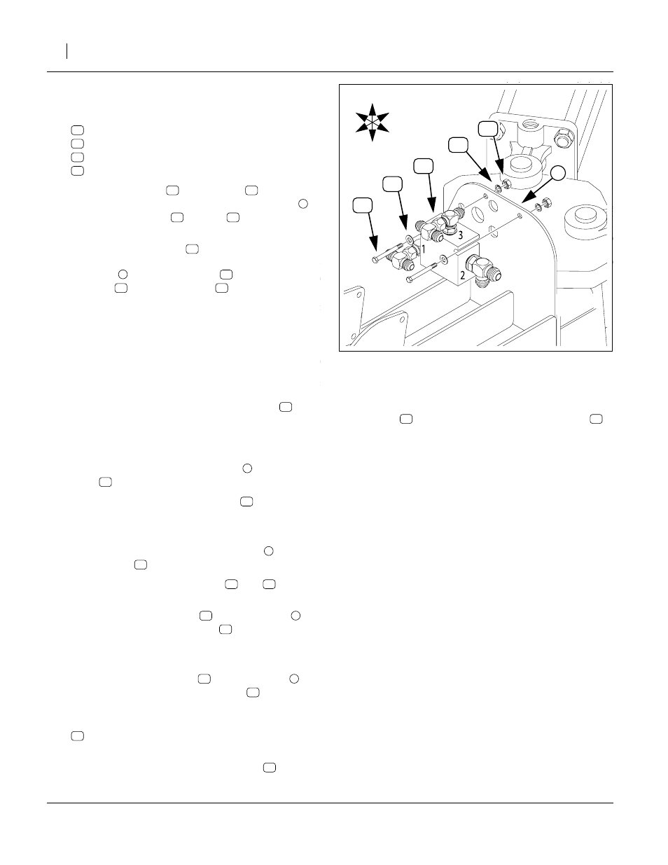
3S Shuttle Valve Installation
Refer to Figure 7
35. Select two sets of:
36. Place a flat washer
the bolts through the top holes of the bulkhead
Place a lock washer
and nut
the the threads. Spin the nut on just a few turns.
37. Select the shuttle valve
With Port 1 to drill Right, place the valve against the
bulkhead
between the bolts
washers
. Tighten the nuts
cations.
3S Shuttle Valve Hoses
Step 38 through step 42 re-connect the hoses discon-
nected at step 31.
Refer to Figure 8 on page 7
38. Identify the two existing 20in or 21in hoses
nected to the top Ports P of the pressure control
valves.
Re-connect the other end of these hoses to the left
and right ports of the top swivel tee
at the shuttle
valve
Port 3.
39. Identify the two existing 18in hoses
connected to
the bottom Port T tee of the pressure control valves.
Re-connect the other end of these hoses to the lat-
eral ports of the right forward swivel tee
shuttle valve
Port 1.
40. Identify the tractor circuit hoses
and
marked
41. Connect the “Lower” hose
the top tee at the shuttle valve
Port 3.
Note: If the drill is equipped with a filter, this is the hose
connected from the filter.
42. Connect the “Raise” hose
the right side tee at the shuttle valve
Port 1. This
port is not visible in the Figure.
43. Select two new:
811-531C HH1/4R2 018 9/16FJIC9/16MORB90
44. Connect the 90 degree ORB end of these hoses to
the bottom Port (3) of each check valve
45. Route the JIC end of each hose to the JIC ports of
the tee
at the left Port 2 of the shuttle valve
46. Tighten all hose connections to torque specifica-
tions.
47. Continue at “Closeout” on page 21.
FigureSpacer
Figure 7
Install 3S Shuttle Valve
18749
U
D
F
B
L
R
4
4
12
6
7
17
8