3s check valve installation, These gauges are re-installed at step 23, Step 22. note which hose is which (b – Great Plains 3S-3000 Installation Instructions User Manual
Page 4
Great Plains Mfg., Inc.
4
Open Center Hydraulic Kit
194-149M
09/05/2012
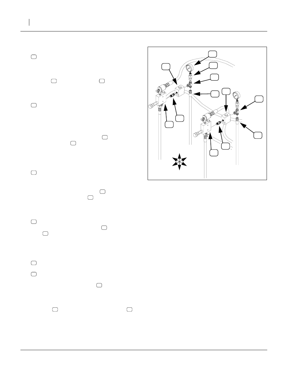
3S Check Valve Installation
Refer to Figure 4
16. Select two new:
811-636C AD 9/16MORB STRAIGHT UNION
Make sure the jam nut is fully threaded onto the
adaptor.
17. At the lower rear valve Port R of each pressure con-
trol valve
, screw in the union
integral hex nut (NOT the end with the jam nut).
Tighten to 9/16ORB specification.
18. Select two new:
810-343C VALVE PO CHECK 2:1 W/9/16FORB
Note: These valves are stamped
85050146
, and if
shaken gently, do not rattle.
(The third valve, assembled at step 25, is a shuttle
valve, and does rattle.)
19. Screw Port 2 of each check valve
onto the other
end of the adaptor
installed at step 17. Turn until
finger tight, then back off until the side of the valve
with the hex head cartridge is Up and Port 3 is
down. Tighten the jam nut to 9/16ORB specification.
20. Select two new:
811-439C TE 9/16MORB 9/16MJIC 9/16MJIC
This is the symmetrical MJIC/MORB tee. There are
four of these in the kit.
21. Screw the MORB port of the tee
Port 1 of each check valve
. Screw until finger
tight, then back off until the JIC ports are vertical.
Tighten the ORB jam nut to 9/16ORB specification.
22. Locate the disconnected hoses:
At the lower port of each new tee
, reconnect the
hose
to the cylinder base ends that was discon-
nected at step 14. Do not use pipe thread sealant
on these or any JIC fittings. Tighten to 9/16JIC
specification (see page 21).
23. Select two new NPT swivel adaptors:
and the saved gauges:
810-300C PRESSURE GAUGE 3000 PSI
Apply liquid pipe thread sealant to the gauge MNPT
threads and screw the adaptor
Tighten to 1/4NPT torque specification (see
page 21).
24. At each valve, screw the JIC end of the gauge
assembly
onto the top port of the new tee
Orient the gauge to face forward, and tighten the
JIC connection to JIC torque specification.
BASE END
, CENTER OPENERS
R
OD END
, CENTER OPENERS
BASE END
, WING OPENERS
R
OD END
, WING OPENERS
1200
1200
600
600
0
0
3000
3000
1800
1800
2400
2400
ps
i
psi
1
2
3
P
G
T
R
R
T
2
3
1
P
G
FigureSpacer
Figure 4
Install 3S Check Valves
16303
U
D
F
B
L
R
20