3s-3000 and 3s-4000 installation, 3s control valve disassembly, Warning – Great Plains 3S-3000 Installation Instructions User Manual
Page 3
Great Plains Mfg., Inc.
3S-3000 and 3S-4000 Installation
3
09/05/2012
194-149M
3S-3000 and 3S-4000 Installation
Step 11 through step 47 are for 3S-3000, 3S-3000HD,
3S-4000 and 3S-4000HD drills only. For 2S-2600 drills,
installation instructions begin on page 9 (s/n DD1161-) or
page 15 (2S2600HD or 2S-2600 s/n DD1162+).
3S Control Valve Disassembly
!
WARNING
High pressure fluid hazard. Pressurized fluid may still be
present. Escaping fluid under pressure can penetrate the skin,
causing serious injury. Wear protective gloves and safety
glasses or goggles when working with hydraulic systems.
Crack fitting slowly. Use a piece of paper or cardboard, NOT
BODY PARTS, to check for suspected leaks. If an accident
occurs, seek immediate medical assistance from a physician
familiar with this type of injury.
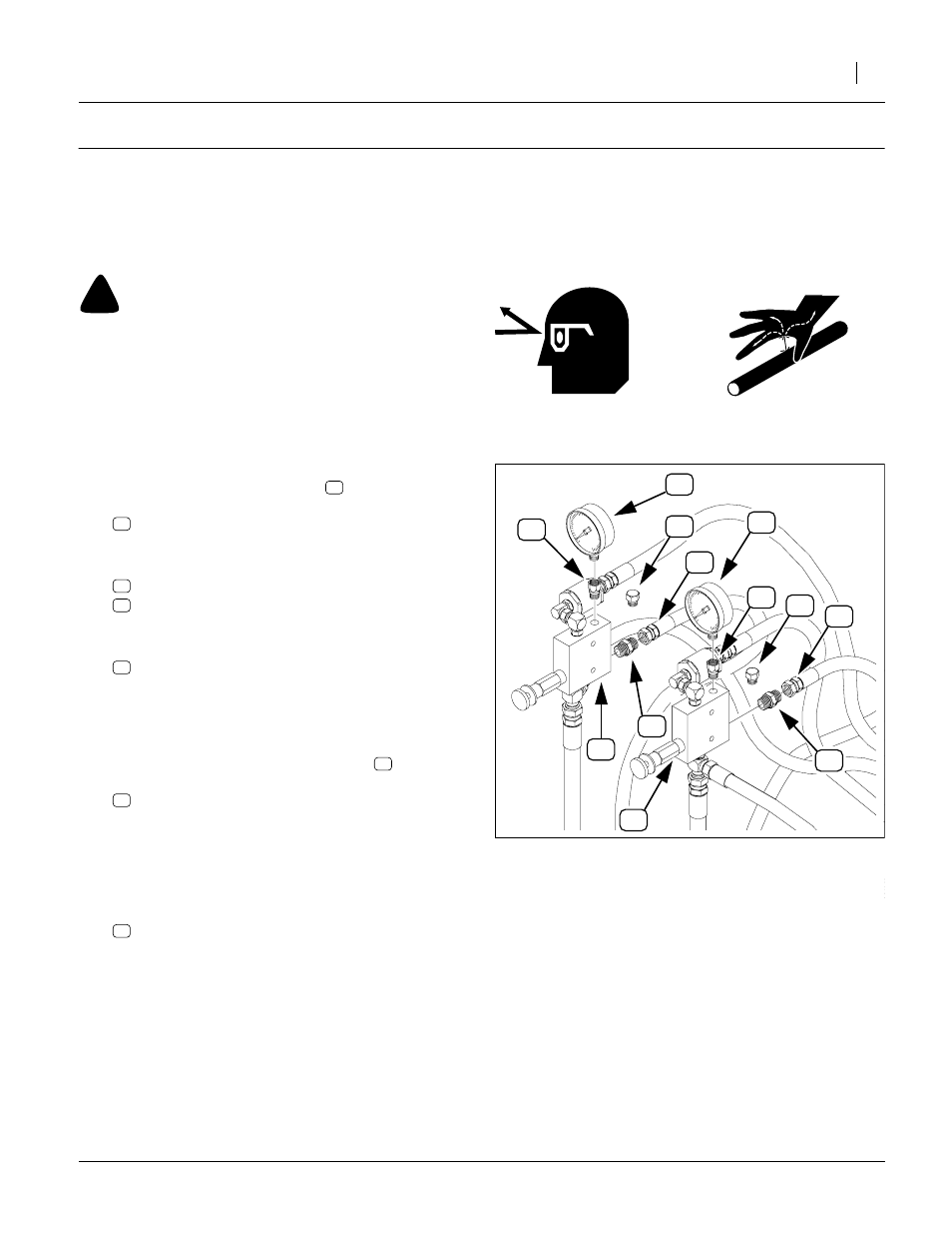
Refer to Figure 3
11. At each pressure control valve
, remove and
save:
810-300C PRESSURE GAUGE 3000 PSI
These gauges are re-installed at step 23.
12. At the top rear Port G of each pressure control valve
, remove:
811-677C AD 9/16MORB 1/4FNPT
These two adaptors are not re-used.
13. Select two new:
Install these plugs in the top rear valve holes previ-
ously occupied by the gauge adaptor. Tighten to
9/16ORB specification (see page 21). Do not use
pipe thread sealant on these, or any ORB fittings.
14. At the rear lower Port R of each valve
nect the hose to the cylinder base ends:
These hoses are re-connected to new fittings at
step 22. Note which hose is which (by where it is
routed to), so that it can be reconnected to the cor-
rect (same) valve assembly after the new valves
and fittings are installed.
15. Remove two:
These adaptors are not re-used.
1200
0
3000
600
2400
psi 1800
N
ERS
E
NERS
R
S
R
S
1200
600
0
3000
1800
2400
psi
P
G
T
R
R
T
P
G
FigureSpacer
Figure 3
Disassemble 3S Valves
16302