Install 3p500/3p600 shaft and sprockets – Great Plains 3P606NT Assembly Instructions User Manual
Page 7
Great Plains Mfg., Inc.
Installation Instructions
7
04/02/2009
133-140M
Install 3P500/3P600 Shaft and Sprockets
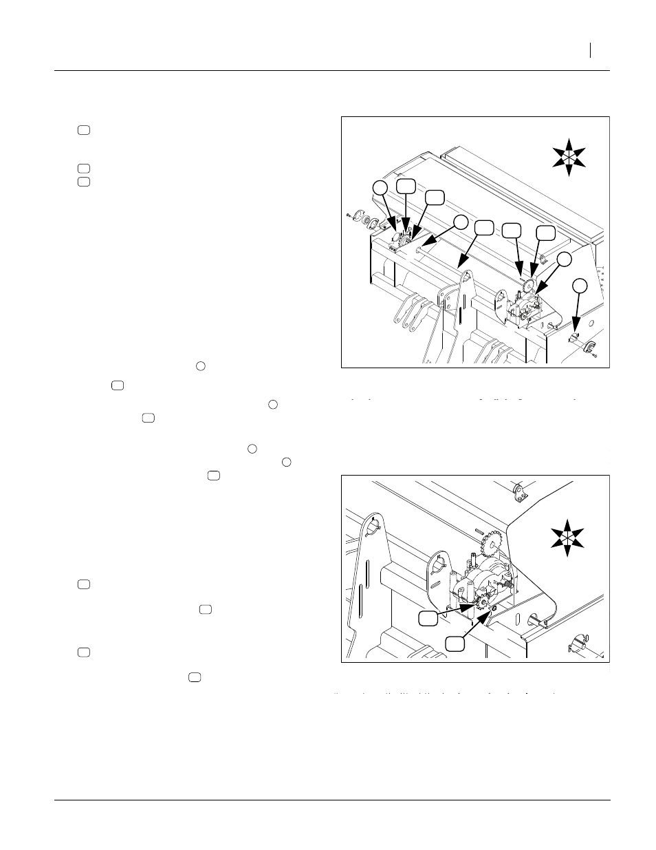
Refer to Figure 10
22. Select the shaft in your kit, one of:
133-037D SGS/AUXILLARY DRIVE SHAFT
133-052D 5’ SGS DRIVE SHAFT
and one each new:
808-170C SPKT 40B17 X 3/4BORE W/KW&SS
808-100C SPKT 40B22 3/4B W/K.W. &SS
As necessary, back out the set screws in the
sprockets so that the sprockets can slide freely on
the shaft.
Note: The shaft has keyways of different lengths on each
end. The end with the shorter keyway is the right
end. The end with the longer keyway is the left
(gearbox) end. The shaft may be inserted in the
drill from either side, as long as the sprockets are
correctly oriented. These steps use the left side.
Note: The sprockets are not symmetrical. For ease of
future maintenance, the set-screw side is oriented
to drill center.
23. Insert the right (short keyway) end of the shaft
through the new bearing
Note: Keys
are installed at step 31 and step 35.
24. As the shaft passes behind the gearbox
, add the
22T sprocket
, with the set screw side facing
right.
25. As the shaft nears the right bearing
passing through the right-most brace-plate
any), add the 17T sprocket
side facing left.
26. Adjust lateral shaft position so that about equal
lengths of shaft end are exposed at the end panels.
Rotate shaft to ensure it spins freely. Secure both
bearing lock collars.
Refer to Figure 11
27. Select one each new:
808-160C SPKT 40B12 X 36T SPLINE BORE
Place the spline sprocket
, raised hub side first,
onto the left front gearbox shaft.
28. Select one each new:
800-141C SNAP RING EXT F/PEERLESS G.B.
Secure spline sprocket
to gearbox shaft with
snap ring.
Figure 10
Install 3P500/600 Shaft
18655
1
2
3
4
U
D
F
B
L
R
1
Figure 11
3P500/600 Gearbox Sprocket
18655
U
D
F
B
L
R
4
3