Fertilizer range gears, Setting variable rate gearbox – Great Plains YP1630F-1670 Material Rate User Manual
Page 20
18
Great Plains Manufacturing, Inc.
YP1630F
401-832B
2012-12-04
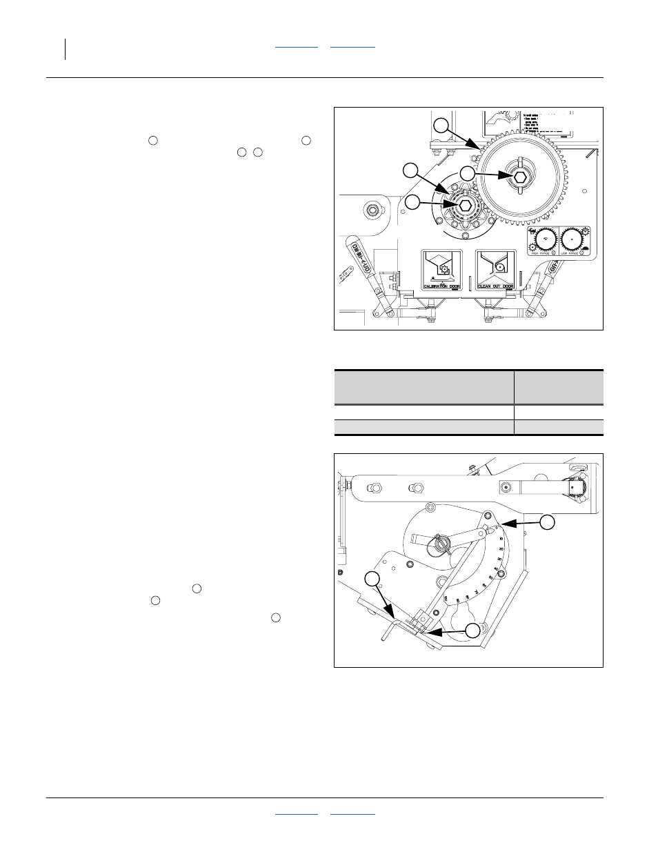
Fertilizer Range Gears
Refer to Figure 9
The meter flute shaft
is driven by the agitator shaft
through a pair of interchangeable gears
,
positioning of these gears creates two final drive ranges.
Each rate chart is based on a specific Final Drive Range.
The Ranges are:
• “High” range, which is used for higher fertilizer rates
• “Low” range, which is used for lower fertilizer rates
The two seed meter shafts are labelled “DRIVING” and
“DRIVEN”.
The “DRIVING” shaft is the upper/forward shaft.
The “DRIVEN” shaft is the lower/rear shaft.
Refer to the Seed Rate Chart (or Fertilizer Rate Chart),
the table below, and Figure 9 for setting the seed meter
final drive range.
1.
Remove the lynch pins from the gear ends of both
shafts.
2.
Remove and position the gears as shown in the table
above.
3.
Secure with lynch pins.
Setting Variable Rate Gearbox
The variable rate gearbox allows an arbitrarily variable
meter drive speed to attain a wide range of metering
rates. The ratio of gearbox input speed to output speed is
controlled by the position of a gearbox control arm. The
control arm has an indicator that points to a scale
marked in degrees. The Fertilizer Rate Charts show the
rate for each degree setting.
Refer to the rate charts and set the variable rate gearbox
control arm to its scale setting for the target rate.
To adjust the Variable Rate Gearbox:
Remove the hairpin cotter
securing the gearbox
adjustment crank
2.
Rotate crank until the control arm indicator
points
to the scale setting that matches the rate from the
chart, or as determined by calibration.
3.
Re-insert the hairpin cotter.
Note: The variable rate gearbox operates optimally
between 30 and 70. If your rate is listed on both the
Low Range and High Range charts, select the
chart where your rate results in a gearbox control
arm setting between 30 and 70. Settings below 20
degrees are not recommended. When the control
arm is set above 70 degrees, large movements of
the arm result in small changes in rate.
Figure 9
HIGH Final Drive Range
34500
FINAL DRIVE
RANGE
DRIVING
DRIVEN
LOW RANGE
17 Tooth Small
54 Tooth Large
HIGH RANGE
54 Tooth Large
17 Tooth Small
2
1
3
4
DRIVING
DRIVEN
3
4
Figure 10
Variable Rate Gearbox at 0
34501
5
6
7