0 battery and power supply specifics – Monarch Instrument Phaser-Strobe pbx User Manual
Page 21
E-17
8.0
BATTERY AND POWER SUPPLY
SPECIFICS
The Phaser-Strobe pbx is fitted with rechargeable NiMH (Nickel Metal
Hydride) batteries. These batteries contain fewer toxic metals than NiCd
(Nickel Cadmium) and are currently classified “environmentally friendly”.
They also have 30% more capacity than NiCd batteries of the same size.
Like NiCds, NiMH batteries are prone to self-discharge - 10 to 15% of
charge is lost in the first 24 hours then continues at a rate of 0.5 to 1% per
day. For maximum performance, charge the batteries just prior to use.
When not in use, the batteries should be charged at least every three months,
otherwise the battery capacity will be reduced or the batteries may become
unusable.
Charge the batteries before use and allow 3-5 cycles of charging and
discharging for batteries to reach full capacity.
The enclosure contains control electronics to properly and safely charge the
batteries. Never remove the batteries from the enclosure and attempt to
charge externally. Always use the charger supplied (PSC-pbxU).
8.1
Low Battery Indication
When the batteries are charged, there will be no battery indication.
When the batteries are low, the Low Battery icon will blink in the
display. The strobe may still be used for a short time.
Low Battery Icon = Outline blinking (very little time left)
The strobe has a protection feature that prevents the strobe from
operating if the battery voltage is too low. This condition is indicated
by no flash and the display shows “LO BAT”. At this time the
S-4
2.2
De Entrada / Las Conexiones de salida
El Phaser-Strobe pbx tiene los gastos de la entrada y la produccion en
el lado izquierdo del estroboscopio. Estos pueden ser utilizados para
provocar o sincronizar externos (margarita que encadena dos o mas
luces estroboscopicas). Estos gatos aceptan 1/8” (phone 3.5mm) tapa
(de entrada-estereo, la produccion – mono). La entrada y la produccion
son TTL compatibles. Veal as figures 2 y 3 para el detalle de la conexion
del conector.
La opcional ROS-P (Sensor Optico Remoto), la MT-190P (Magnético),
o IRS-P (Infrarrojo) sensores pueden ser utilizados también provocar
la unidad.
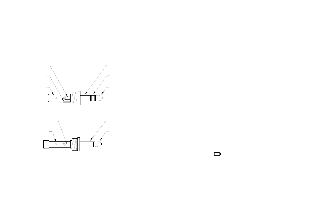
Salida Pulso
Comun (GND)
Comun (GND)
Salida Pulso
Figura 3 Detalle de Salida del Conector (Mono Tapon)
Señale la Entrada
+6V Fuera al
Sensor
Comun (GND)
Comun (GND)
+6V Fuera al
Sensor
Señale la Entrada
Figura 2 Detalle de Entrada del Conector (Tapon Estereo)