Wx 2 hardware overview, Display overview – Weller WX2 User Manual
Page 26
WX 2
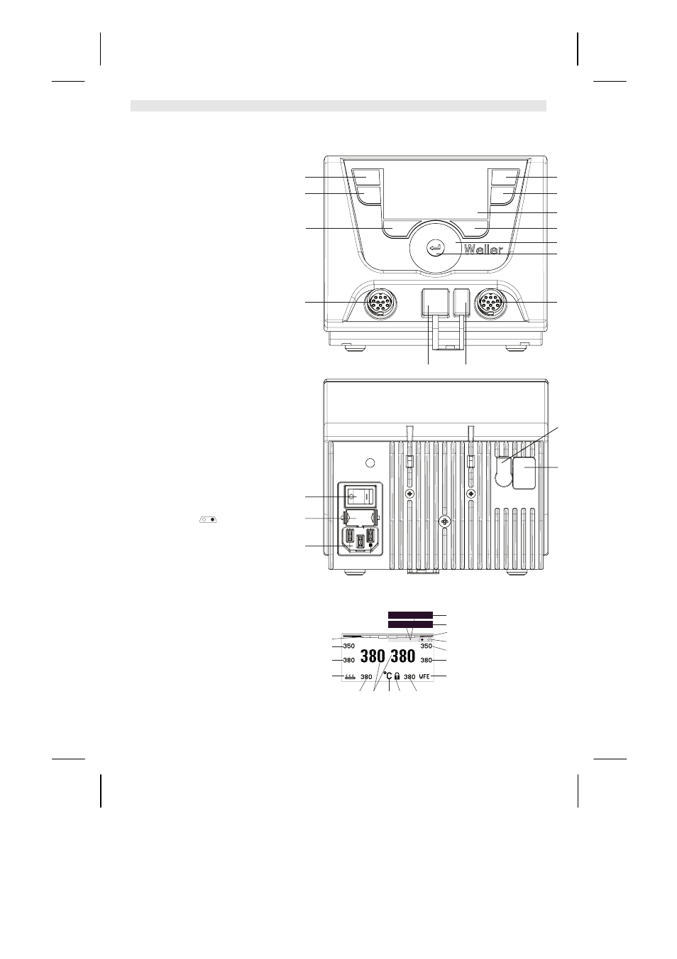
Fig. 1: Hardware Overview
Fig. 2: Display Overview
WX 2
Hardware Overview
1 Control button, left
2 Control button, left
3 Control button, right
4 Control button, right
5 Display
6 Selection button (set-point
temperature, exit parameter
menu, auxiliary device
parameters)
7 Turn-and-click wheel
8 Enter button
9 Right receptacle for soldering
tool
10 USB port
11 RS232 port
12 Left receptacle for soldering
tool
13 Selection button (nominal
temperature, auxiliary device
parameters)
14 Equipotential bonding bush
15 RS232 port
16 Mains connection
17 Mains fuse
18 Power switch
Display Overview
19 AUTO-OFF
20 Standby temperature
deactivation
21 Power indicator
22 Left (or right
)
configuration display
23 Fixed temperature 1, right
24 Fixed temperature 2, right
25 Auxiliary device
(rear port)
26 Active set-point/ fixed
temperature, right
27 Lock
28 Temperature units °F/°C
29 Actual tool temperature (left,
right)
30 Active set-point/ fixed
temperature, left
31 Auxiliary device
(front port)
32 Fixed temperature 1, left
33 Fixed temperature 2, left
15
14
18
16
17
2
1
13
12
3
4
6
9
7
8
5
11
10
23
24
28
21
29
25
Off
27
20
19
30
26
Standby
33
32
21
31
22