Weller WRK User Manual
Page 6
6-9
WRK
A 4
B 4
A 2
1
2
B 2
5.2
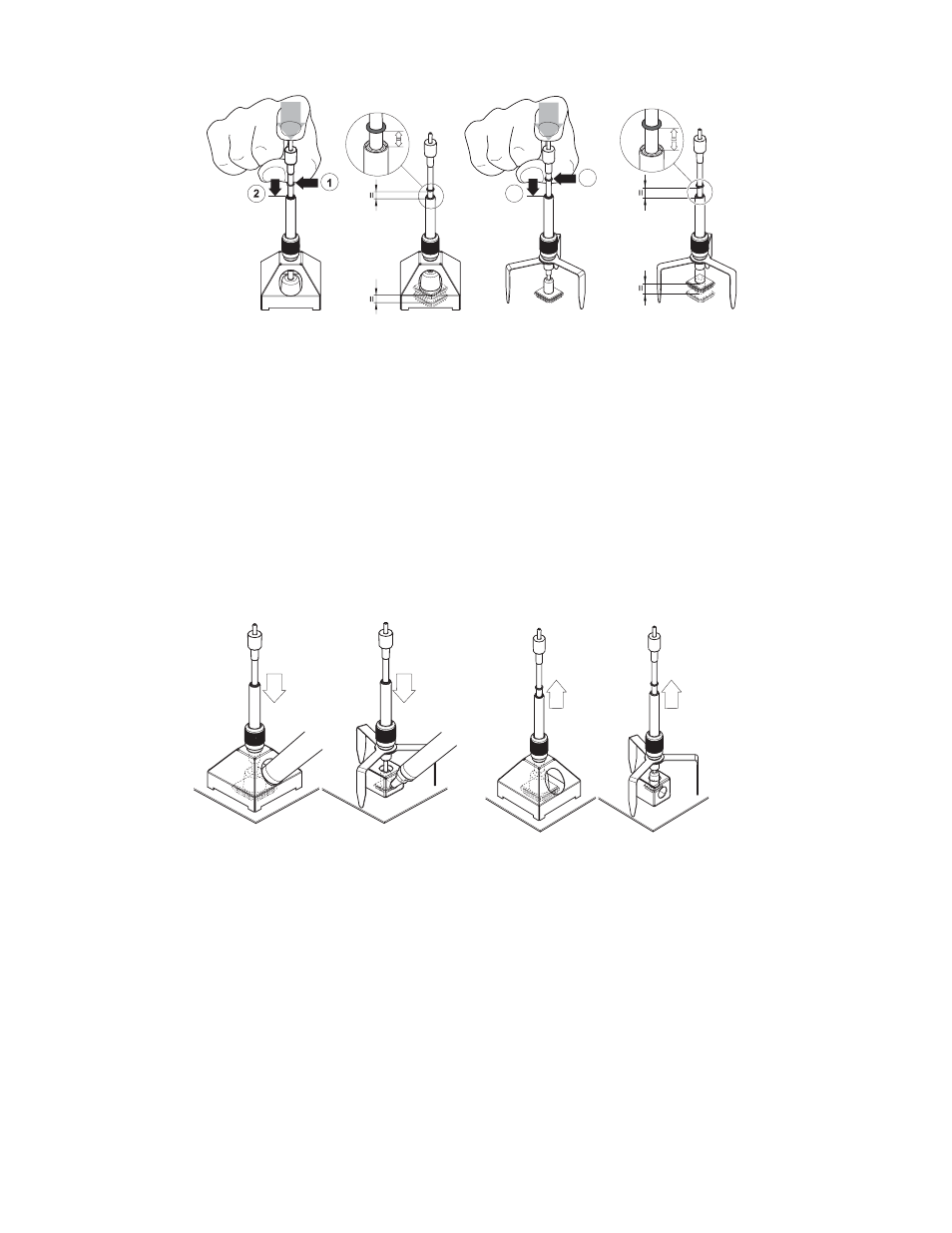
Preparing for Component Pick-up
Note Pictures are for illustration use only. Vacuum hose must be
connected and activated for the vacuum pick-up tool to operate.
1. Carefully position the vacuum pick-up tool with mounted reflow
nozzle, (A2) or with the tripod, (B2) over the component.
2. Carefully press the vacuum pick-up tool down .120- .400 ", (3-5
mm) over the component (1) without damaging the component.
3. Switch on the vacuum on the control unit and subject the
component to suction.
4. Slide the marker ring in this position downwards (2).
The marker ring indicates whether the component subjected to
suction is raised (rubber = at top) or not raised (rubber = at
bottom).
5.3 Reflow and Removal of the Component
A 3
B 3
See also other documents in the category Weller Tools:
- WDH 10T (7 pages)
- HAP 200 (6 pages)
- 6966 HEAT GUN (5 pages)
- BP645MP (2 pages)
- BP860MP (2 pages)
- D650 (4 pages)
- DEC1001 (4 pages)
- DS800 (4 pages)
- DTL1000 (3 pages)
- EC1302B (2 pages)
- EC2002M (4 pages)
- ML100 (1 page)
- ML200 (1 page)
- ML500MP (1 page)
- MT1500L (4 pages)
- Cordless Soldering Tool (2 pages)
- WHA 30 P (14 pages)
- TB100PK (2 pages)
- WA2000 (9 pages)
- WCB1 (2 pages)
- WD2M (22 pages)
- WES50 (4 pages)
- WES51 (7 pages)
- WESD51 (7 pages)
- WHA900 (11 pages)
- WHP 3000 (37 pages)
- WLC100 (3 pages)
- WLC200 (2 pages)
- WSB25 (21 pages)
- WQB2000 (9 pages)
- WR2 (65 pages)
- WR 3M (21 pages)
- WS80 (3 pages)
- WSD130 (6 pages)
- WSD80 (6 pages)
- WTCPT (4 pages)
- WTL1000S (5 pages)
- WX2 (128 pages)
- WXMP (72 pages)
- WX120 (56 pages)